Why the Bosco test?
Even though several similar products are already available on the market, their price range is often ridiculously high for a sports club trying to run a simple physical fitness test. As high school students practicing sports after school, we decided to do something about it.
After a little bit of researching on the net, we realized that most of the sensors and data usually featured by such systems aren't even taken into consideration by your everyday athlete. Our new goal: to start cutting down on every unneeded asset.
How does it work?
A laser barrier detects whether the athlete's feet are currently touching the ground or not. For every jump, the delay between two "touching-the-ground" instants is memorized as the ToF (time of flight) for that particular jump. Finally, this information is sent via Bluetooth to a connected Android device, which deducts the JH (jump height) using a simple formula (g being the gravitational acceleration):
JH = (ToF ^ 2 * g) / 8
Technical Implementation: Laser Barriers and ToF Physics
The project reveals the hidden layers of simple motion-to-data interaction:
- Identification layer: The KY-008 Laser and an LDR (Light Dependent Resistor) act as high-resolution optical eyes, detecting every point of your feet's presence as the light beam is broken or restored.
- Conversion layer: The Arduino Mega uses digital I/O pins to receive high-speed laser state changes and coordinate timing tasks in microseconds.
- Processing Logic layer: The Arduino code follows a specialized "sequential decoding" strategy: it only starts the timer when the laser is restored (jump start) and stops the timer when the laser is broken (landing).
- Physics Interface layer: The Arduino performs the math (JH = ToF^2 * g / 8) to calculate the final jump height in cm.
- Wireless Interface layer: Data is sent rhythmically to the HC-05 Bluetooth module to coordinate the jump status in real-time with the Android app.
Hardware Infrastructure
- Arduino Mega 2560: The "brain" of the project, managing high-speed microsecond timing and coordinating the Bluetooth data tasks.
- KY-008 Laser & LDR: Providing contactless and reliable movement monitoring for each of your jumps.
- HC-05 Bluetooth Module: Providing high-speed and reliable data transmission to the Android device.
- OLED Display (128x64): Providing high-definition visual feedback of your jump height and last record locally.
- Breadboard: A convenient way to prototype the first sports-science circuit and connect all components without soldering.
- Micro-USB Cable: Used to program your Arduino and provide the primary power source for the sensor controller.
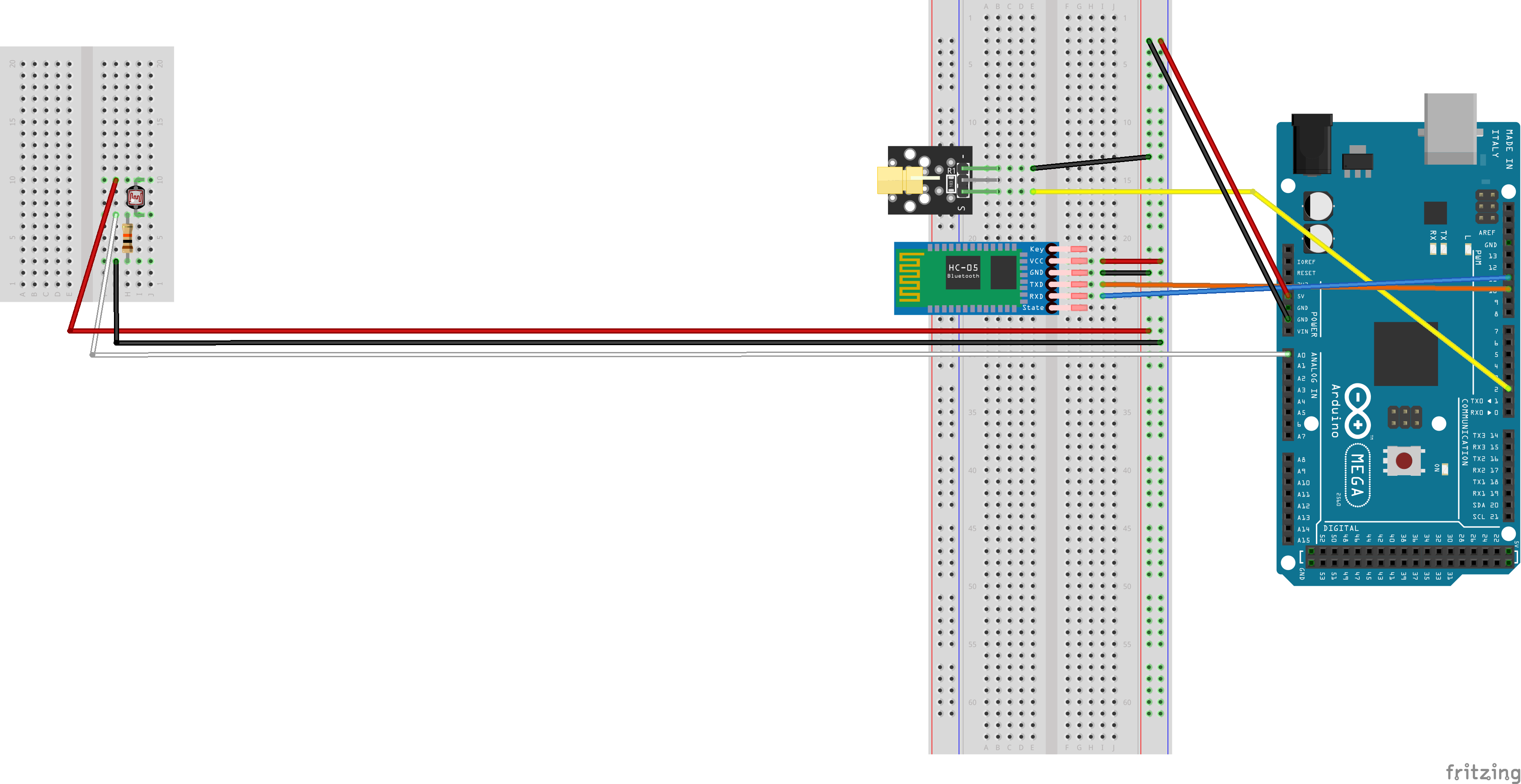
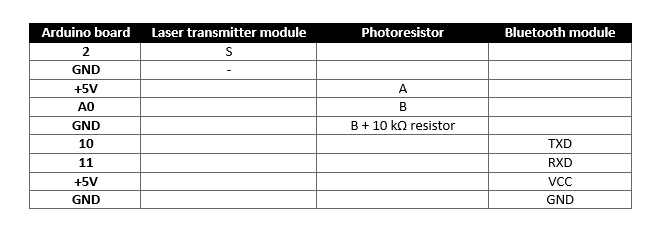
Assembling your circuit
For those of you who just don't feel like downloading any .fzz files, here's how to connect the various components used by the project:
Monitoring and Interaction Step-by-Step
The Bosco test process is designed to be very user-friendly:
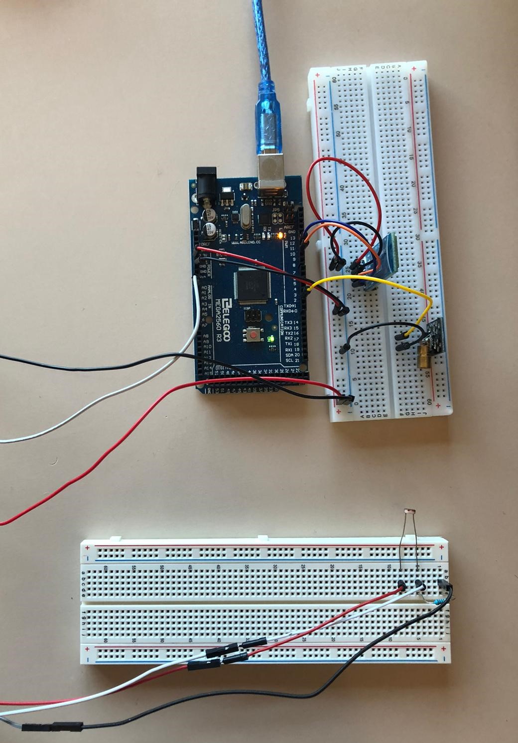
- Initialize Hardware: Correctly seat the laser and LDR on the ground-level and connect to the Arduino Mega as shown in the circuit images above.
- Setup Output Sync: In the
setup()function, initialize the Serial port (for BT) and define the laser pin as anOUTPUT. - Internal Dialogue Loop: The Arduino constantly performs high-performance laser checks and updates the Android dashboard in real-time with the jump score.
- Visual Feedback Integration: Watch as your Android app and the OLED automatically become a rhythmic visual signal, pulsing and following your jump settings.
Uploading the sketch
Follow these simple steps to upload your sketch:
- create a folder named "test_di_bosco" in your sketchbook folder
- download the six files embed below inside your new "test_di_bosco" folder
- open "test_di_bosco.ino" using Arduino IDE: a single window with all of the ".ino" files in it should open
- that's it: you are now ready to upload the entire sketch clicking on "upload" once
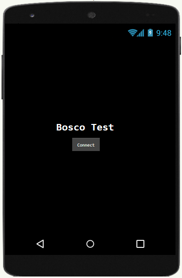
A sample Android application
We chose to use MIT App Inventor 2 (see Apps and online services) to develop our sample application (available for free).
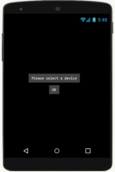
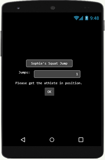
Running the test
[!NOTE] Ensuring precise laser alignment is key to avoiding "False Triggers" during high-intensity jump training!
Future Expansion
- OLED Identity Dashboard Integration: Add a small OLED display inside the laser box to show a "High Score" and the "Last 5 Jumps Mean."
- Multi-sensor Sync: Connect a specialized "Weight Sensor" (Load Cell) to perform higher-precision "Power Output" calculations along with the jump.
- Cloud Interface Support: Add WiFi/ESP32 dashboard to precisely track and log the jump history from a smartphone anywhere in the gym.
- Advanced Velocity Profile: Add specialized "Reactive Strength Index (RSI)" to the code to measure the contact time before the next jump.
Work in progress (maybe)
- ground contact time
- power developed during the jump
- jump frequency
- RSI (Reactive Strength Index)