STORY
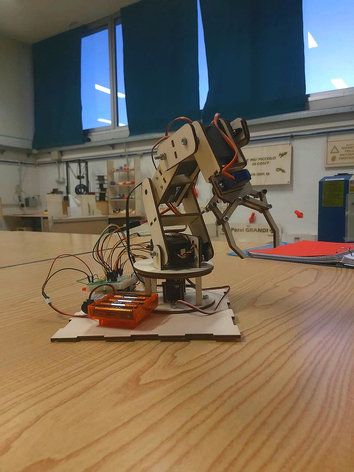
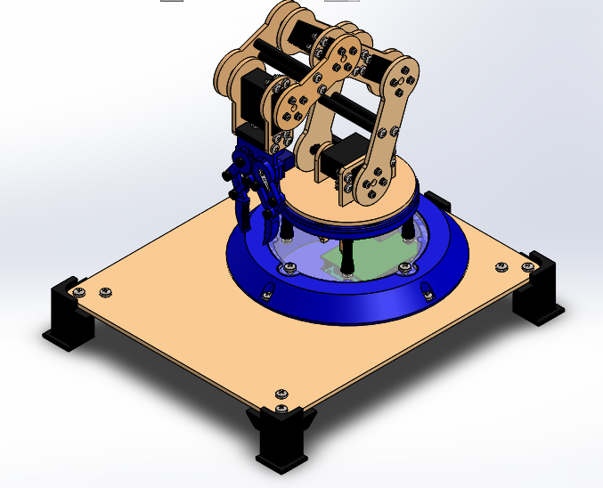
Bracc.ino is a simply articulated arm, composed by 6 servomotors, controlled via bluetooth by an Arduino Joypad. It was born as a school project, and it have the purpose to simulate an industrial robot. After different attemps we could find the right way to proceed and we could move a robot.
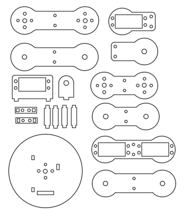
For create the final prototype we use diffrent production methods, like using the laser-cutter for the structure and the 3D printer for pins, gripper and base.
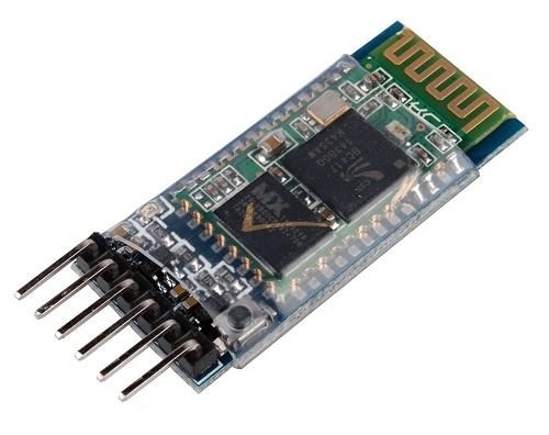
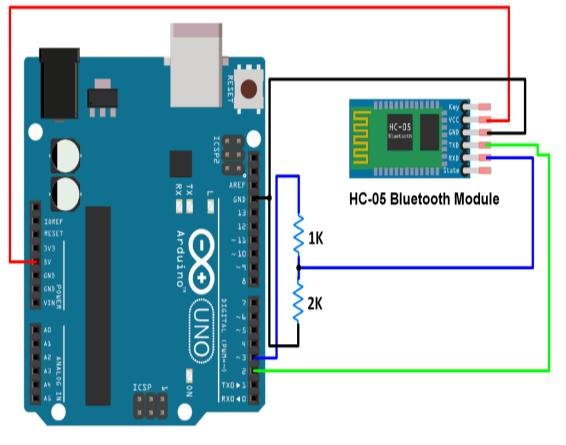
The arm movements are controlled by a Arduino board. We can send information about which movement to do, using a bluetooth communication between the two board. We decide to use the sensor HC-05 for do this.
BLUETOOTH COMMUNICATION
Bluetooth communication consist in sending and receiving information via radio frequency. It can be useful to sending data without the necessity of a wire. So we decide to find a way to create a joypad for our robotic arm. And we found out that it can be possible using Arduino. Using the Bluetooth module HC-05, we can receive data by a devide but, programming the sensor, we can also send data to another HC-05. So we finf out a method to programme and change the module configuration. The module that send data to the other, is called MASTER, the receiver, instead, is called SLAVE. So the two configuration are a bit different, but have some common point. Basically the main point are:
- Connect the two Arduino with the HC-05 sensor, powering the EN pin (or key) with 5V. Then upload an empty sketch and open the serial communication. For make easier the procedure, we can connect at the same time both boards, using two different Arduino IDE windows.
- Now writing some words on the serial monitor, we can change bluetooth configuration.
Slaveconfiguration:serialmonitorsequence
- Write"AT" until the reply is "OK".
- AT+UART=38400. It setting up the baud rate, that for bluetooth is 38400 baud.
- AT+ROLE=0. Set the HC-05 to slave mode.
- AT+CMODE=0. It's used to connect only with paired devices
- AT+PSWD=1234. Set the password. It's important to use the same also for the master sensor.
Master configuration: serial monitor sequence
- Write "AT" until the reply is "OK".
- AT+UART=38400. It setting up the baud rate, that for bluetooth is 38400 baud.
- AT+ROLE=1. Set the HC-05 to master mode.
- AT+RMAAD. Clear previously paird device.
- AT+RESET. Reset the module.
- AT+CMODE=0.
- AT+INQM=0, 5, 9.
- AT+INIT.
- AT+INQ. The last three commands help us to search our slave module. The last command return the address of the devices near the module.
- Now we have to copy the right address. If we have more than one, we can controll the right device paste the address after "AT+RNAME=<address>. It's important to use commas instead of colons.
- Found the right device, write "AT+PAIR=<address>, 9"
- AT+BIND=<address>.
- AT+CMODE=1.
- AT+LINK=<address>
- If we receive an "OK" of reply, we have successfully paired the two bluetooth modules.
For more informations about the pairing procedure, visit the link:
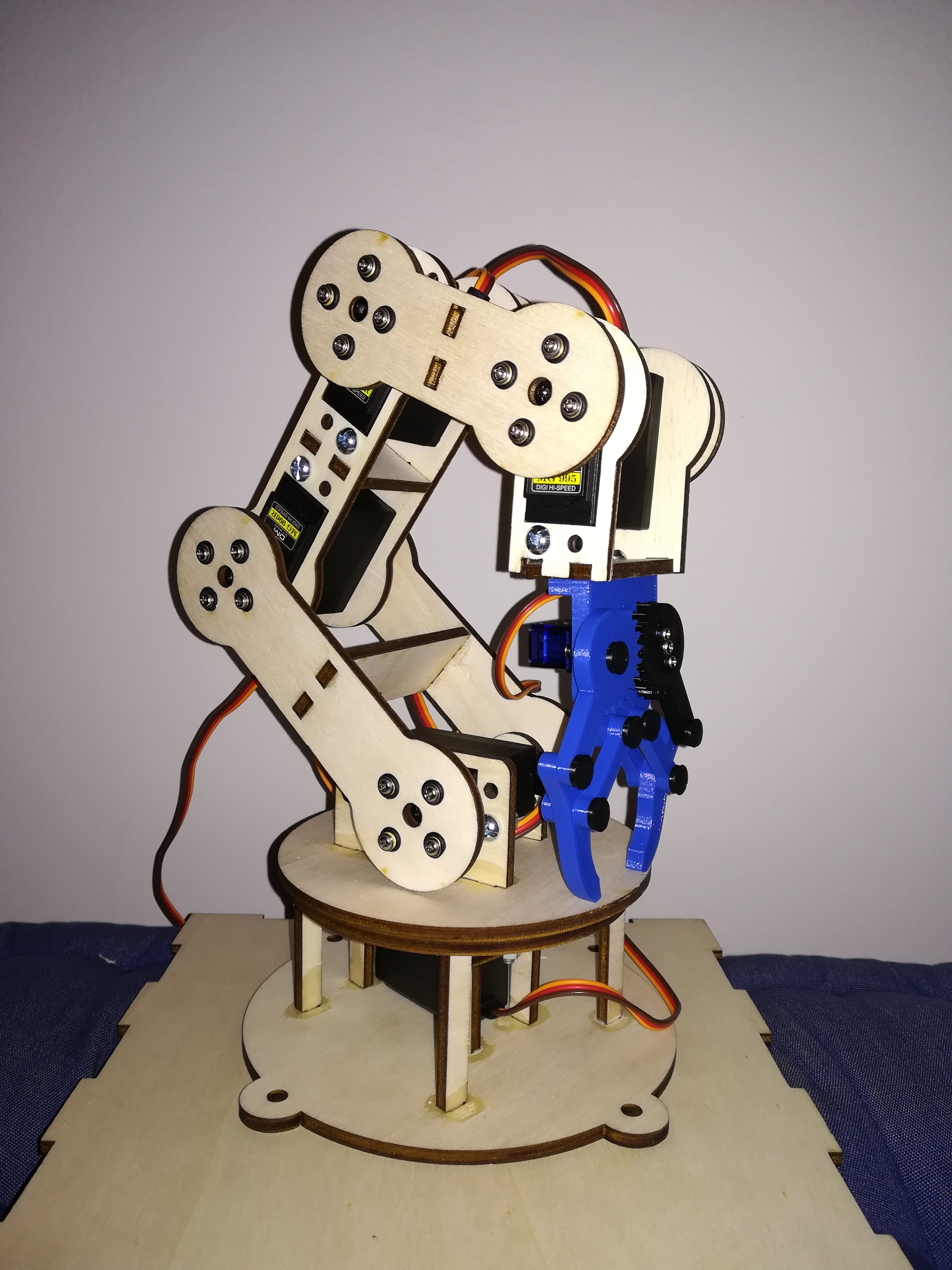
STRUCTURE DESCRIPTION
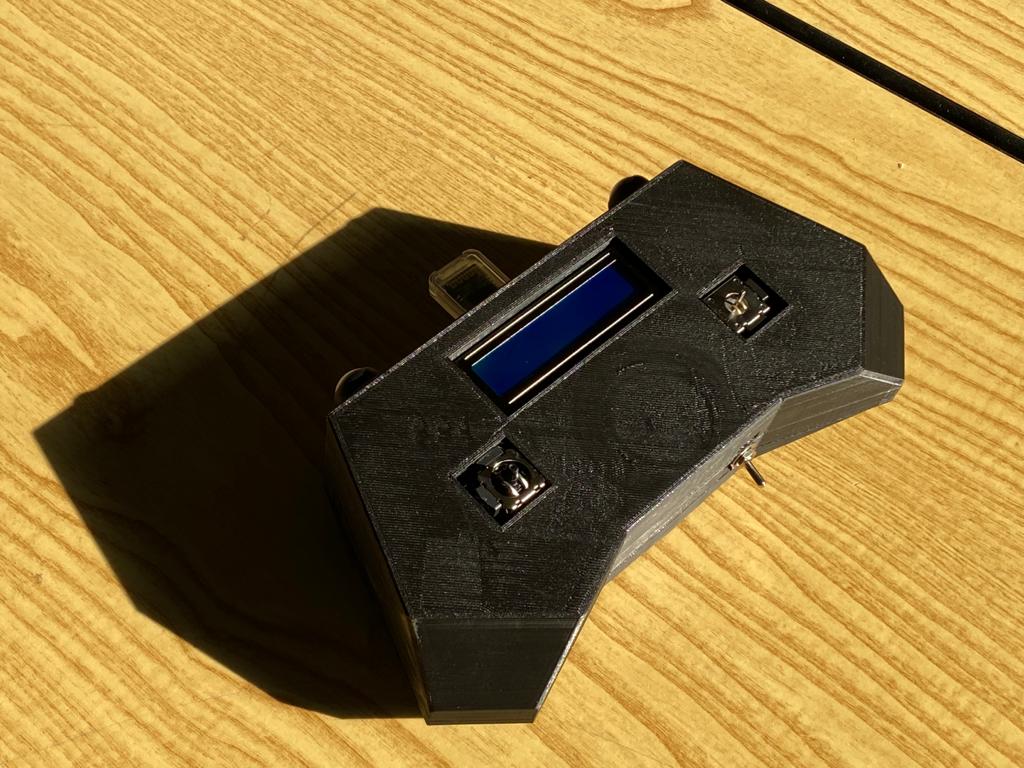
School give us lots of opportunity to learn how to use lasercut and 3D printing tecnology. So we were be able to create an arm structure, starting drawing it on a 3D software, like"SolidWorks". Then we choose, for aesthetic reasons, to produce the structure part using the laser-cut machine, and the 3D Printer for the gripper and base. Also the joystick is created by the 3d printer.
The 3D files can be easy found on the GrabCAD platform at the link:
https://grabcad.com/library/bracc-ino-1
JOYPAD
SERVO
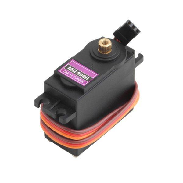
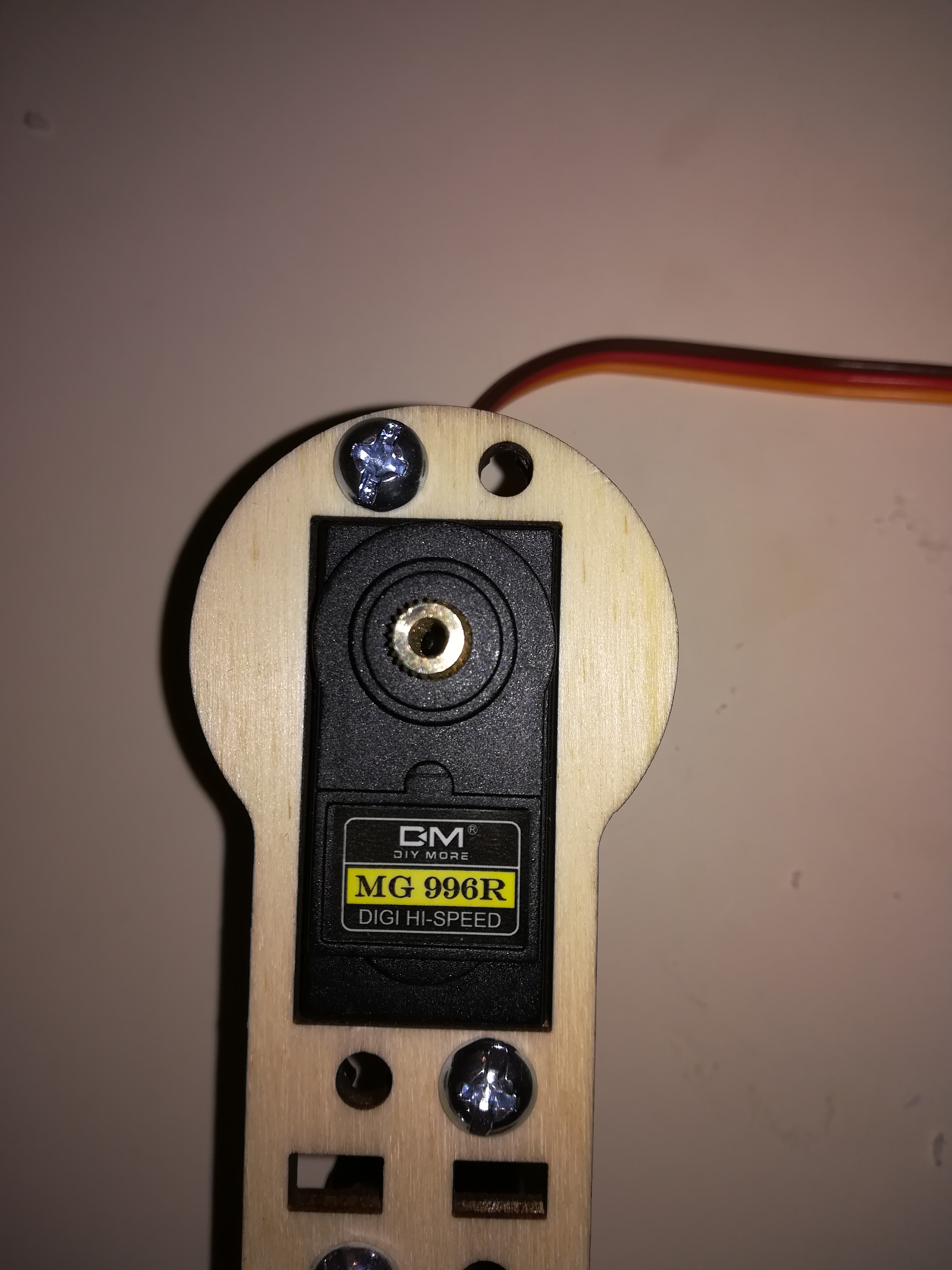
The articulation of the arm are moved usign Servomotors. They are easy to use, with the <VarSpeedServo.h> Arduino library, and we can control the motor angle really easy. But for lift of the structure, we have to use some different servo, with an higher stall torque. The servo MG996R, help us to lift all the arm. Furthermore this servo are a digital type, that is they are more accurated than the normal ones. We also have to use the <VarSpeedServo.h> library instead of the normal <Servo.h> library. The previous one has more fnctions and help us to simulate a more flowing movement. It also has functions for control the servos speed and for move them in a asyncronous way.
This library can be found at the following link:
https://github.com/netlabtoolkit/VarSpeedServo
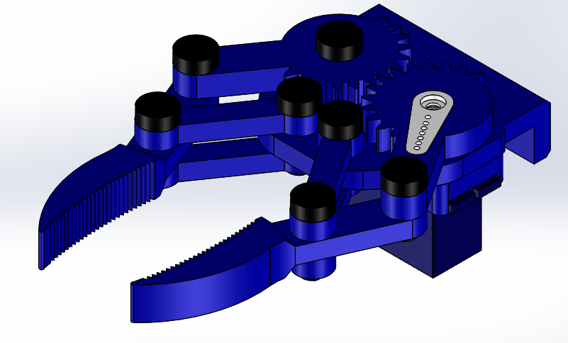
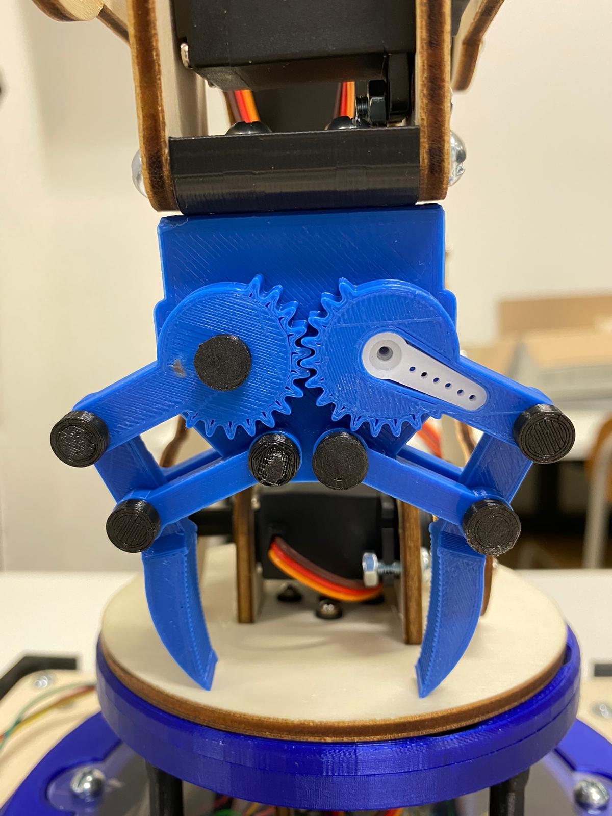
GRIPPER
The robot arm tool is now an easy gripper that can hang small object and move them. It's designed by us and realised by 3d printer. The SG90 servo motor rotate a gear, that moves the other and opne or close the claws.
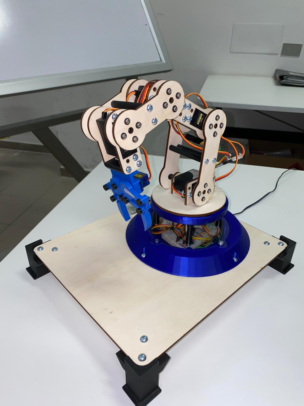
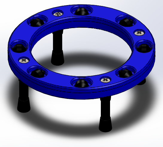
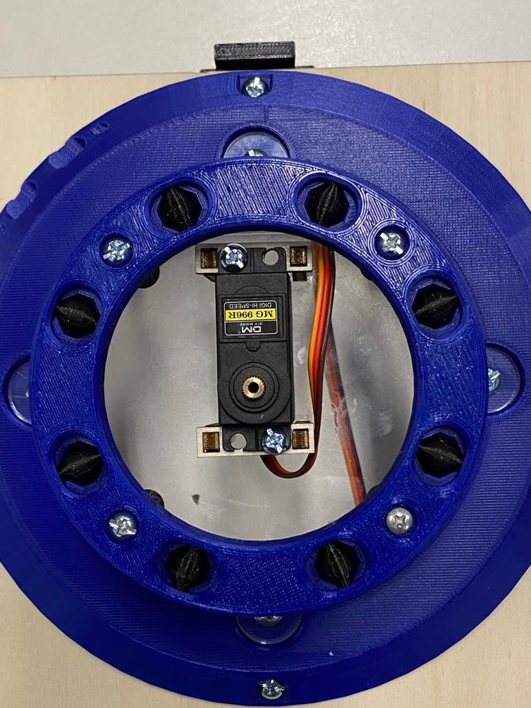
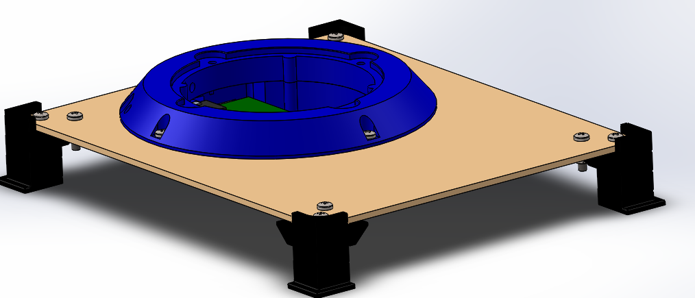
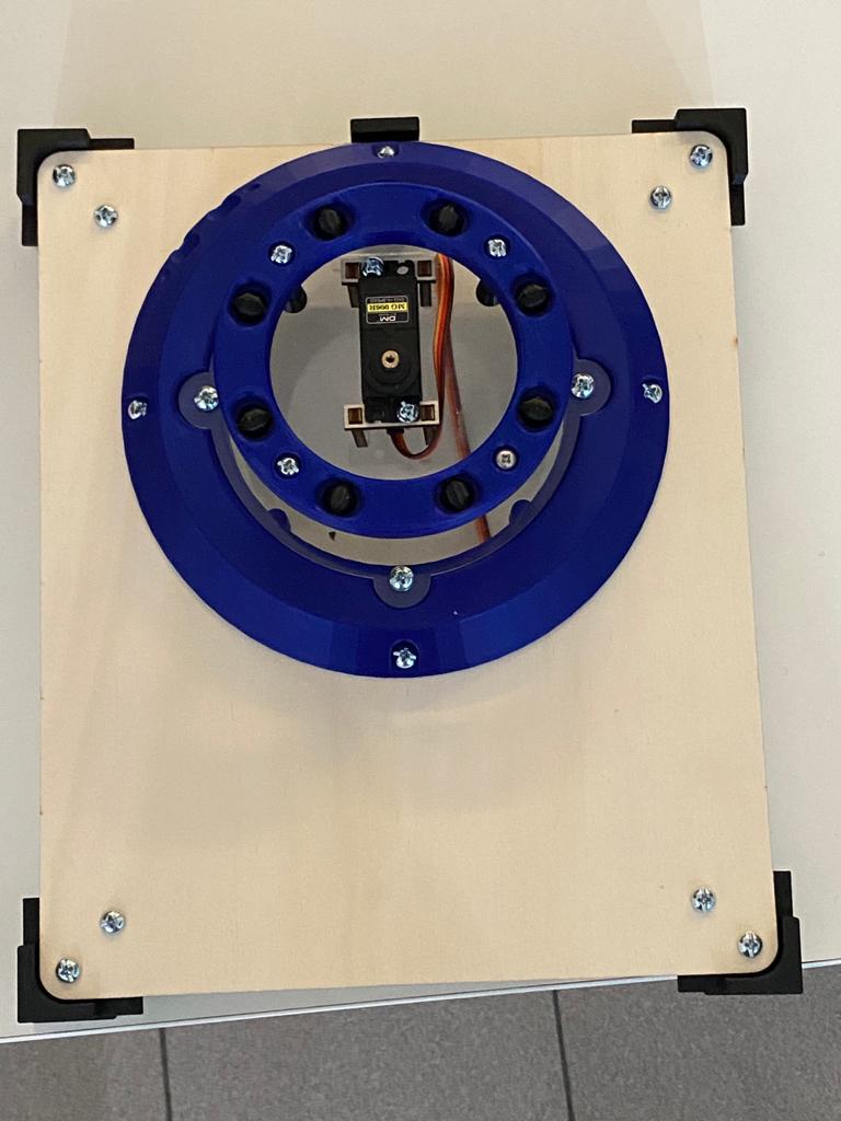
BASE BEARING
Another useful component is the base bearing. It is like an assial ball bearing, but it's fully 3D printed. It has two circular ring with inside some rollers, which have a particular shape for slide without problems. The main function is to help the base rotation, avoiding to creep on a wooden disk.
COMMANDBLOCK - BASE
Under the arm there is a block with inside all the circuits and batteries of the robot. It contains Arduino Board, PCB and recharging batteries. This base cane be disassemplied from the ground, and can be a modular mount to others devices.
CIRCUITS: ARM
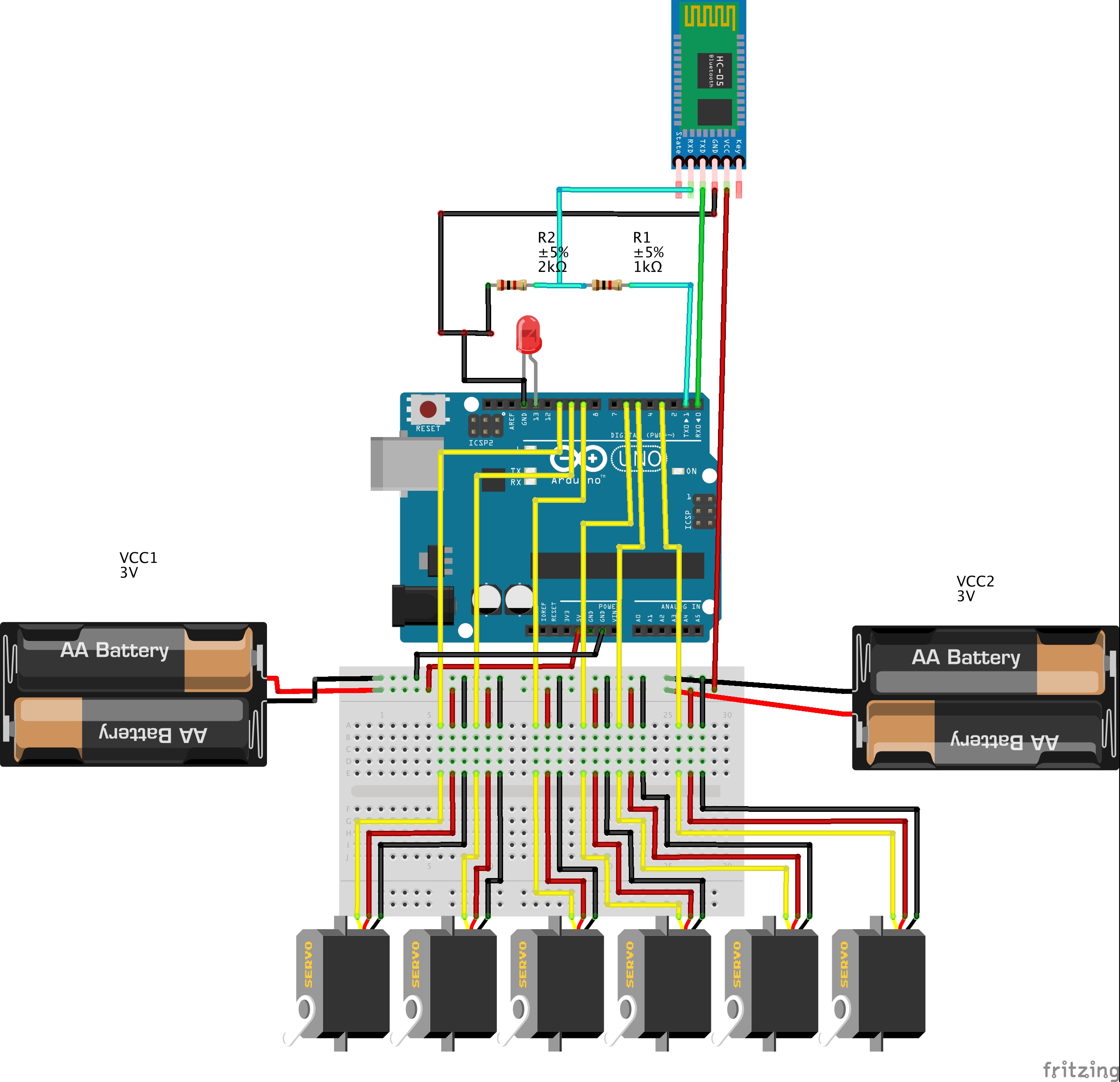
The arm cicuit is composed by the bluettorh wiring with the HC-05 and connect each Servo to GND, 6V and PWM pin. Servos have a different power line, because they have a higher torque with an higher supply.
CIRCUITS: JOYPAD
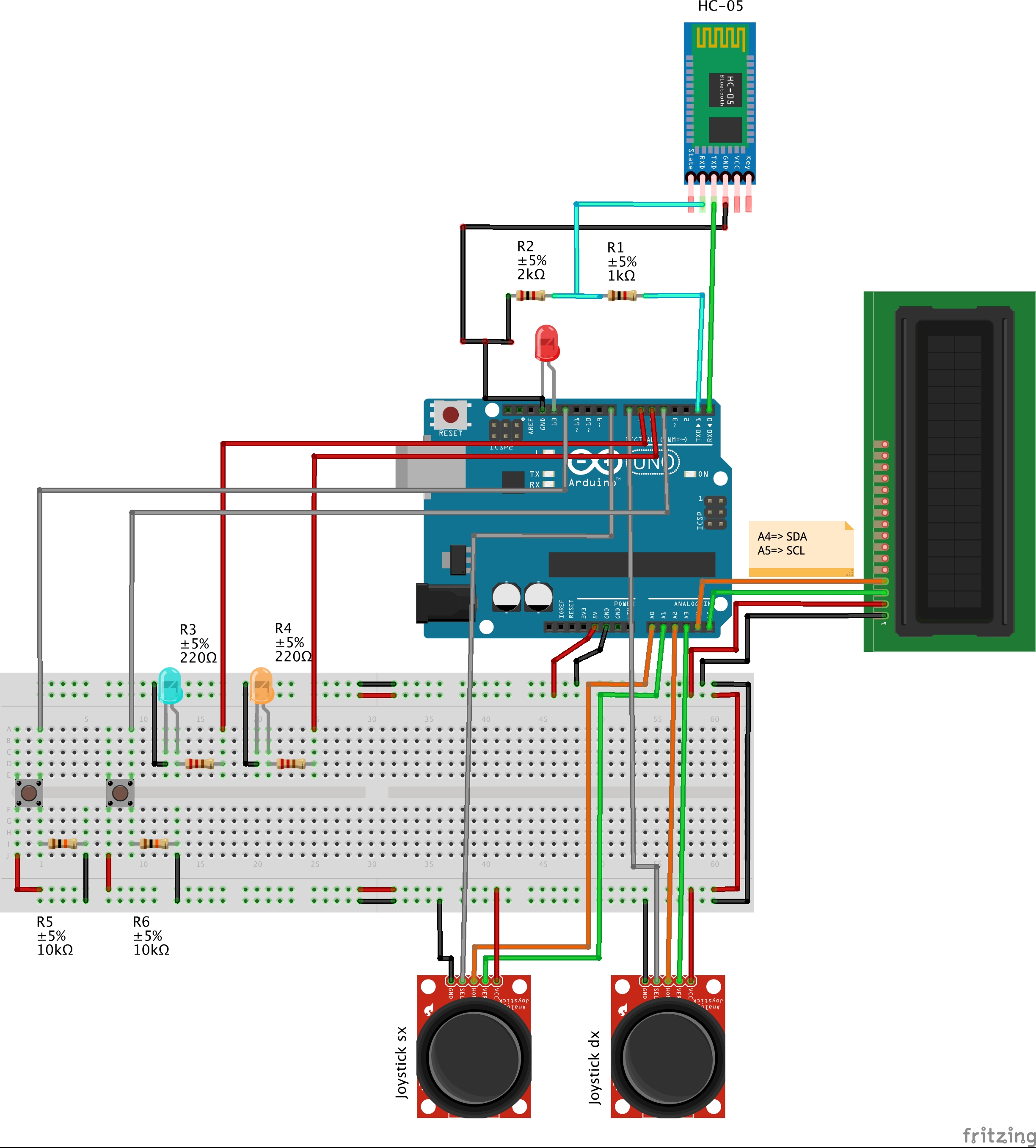
The joystick circuit is composed by the same bluetooth wiring, adding the two joystick, two buttons and a LCD.
The joystick are composed by two trimmer, the value of each trimmer is read by the analog IN pins. The same happen for buttons, but we have to use a digital pin, to read if it's HIGH (pushed) or LOW (not pushed).
The LCD monitor, that we wire to a I2C Module, that decrease the number of connections, print how servo we are moving and their angle. For use it we found a specific library called <LiquidCrystal_I2C>, which can be downloaded here:
https://github.com/fdebrabander/Arduino-LiquidCrystal-I2C-library
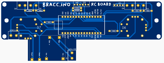
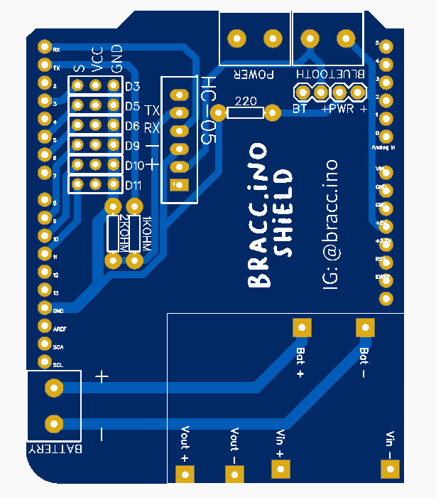
PCB
With the problem of flying wires and unclear circuit, we thought to draw a PCB circuit to connect like a shield to the Arduino Board. We use "EasyDA" site to draw them and we order the parts by the JLC site. In this way, circuits are clearer, smaller and more comfortable to use.
CODE FUNCTIONS
For programming we use the Arduino IDE software, that use a quite simple language of programmation. We have two different code, one for the joystick Arduino and one for the Arm movement.
The main function and actions of the code are explain in the sequent flowchart, for make easier the understanding.
JOYPAD
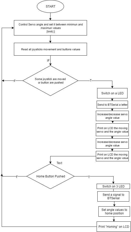
For sending commands, we have created a list of codes, composed by the different letters, that means different things. Every code is matched to a letter or number, sent by the bluetooth communication to the arm.
In both codes there is a "limit()" void, used to control servo angles. If the values are bigger than the maximun or smaller than the minimun, the angle return to the limit value. The max and min was been set testing the servo motor at the first assembly, and they can be easly changed, modifying the variables at the beginning of the codes.
ARM
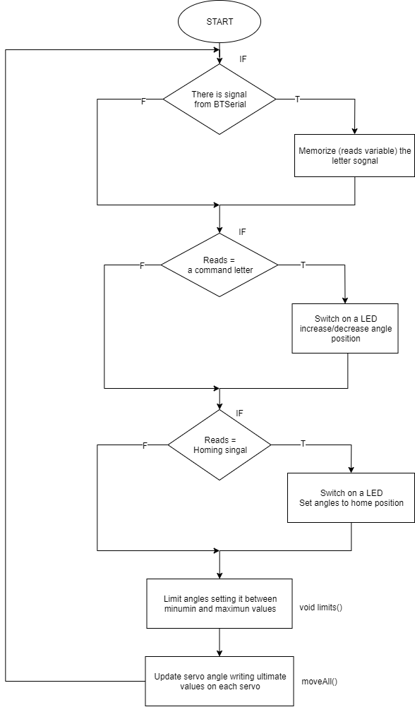
At the beginning of the code, the bluetooth module search for data, and in case of received information, it modify the "reads" variable in the received letter, which correspond to a motion.
Also this code has a "limit void" for control the servo angle.
At the and of the code there is a moveAll() void. We choose to use this function instead of update the servo angle inside the "if" function, because in this way evvery time the loop start/end, the servo angle is updated and the motor remain in tension.
The arm have two modes; the directs mode, which move one by one motors, and the inverse mode, that move all servos, calculating the angle starting by a point coordinate.
Point saving function
An arm intresting function is the point saving method. It can save the arm position and replay it in sequence. On the direct mode, the code memorize the angle value of all the servos, instead on the inverse mode it memorize the coordinate of one pont.
Joystick print on the LCD which point is saved, and alerts when it reaches the maximun number of points (that actually are five, plus the home point at last) and when it resets the memory.
INVERSE KINEMATICS MODE
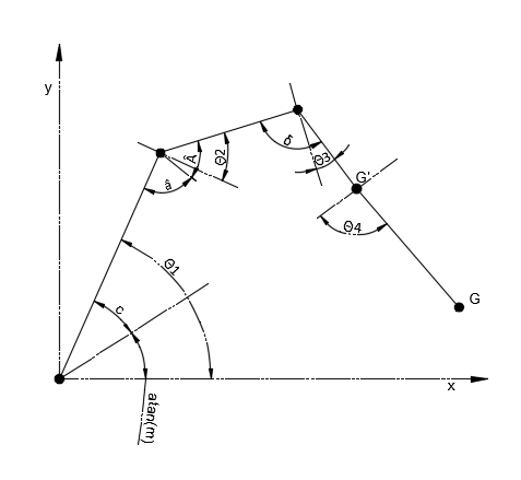
The inverse mode, instead of the direct one, use an algorithm base on inverse kinematics to find all the servos angles. This calculation starts by the coordinate position (x,y) and the orientation of the gripper point. For this calculation we use a geometrical method. As a matter of fact it is based on the costruction of triangles with cosin and sin function, we can calculate all the angles, and translate this values to servos angles.
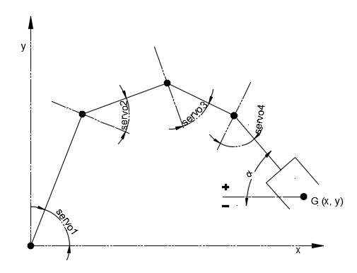
1- Translation in G' Point
First of all we have to translate our G point to the G' point to semplificate the inverse calculation. The y of the G point is also to translate up of 93, for having the origin point coincidente with the first joint.
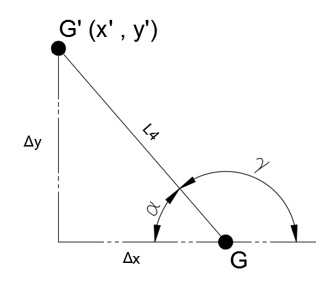
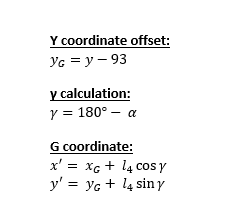
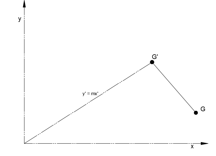
2- Straight line and slope
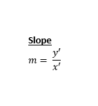
Now we can calculate the slope "m" of the straight line from the cartesian origin to the G' point.
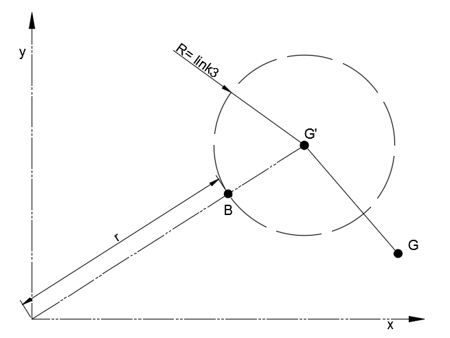
3- Circle intersection
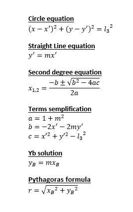
After that we can draw a circle with centre in G' and radius equal to the link 3 lenght. We know the circle equation, so we can find the intersction between the straight line, in B point.
Simplyfing the two equations we can find the Xb equation using the second degree solve method. We can find the a, b and c values by semplificating and collecting the circle and the straight line equations.
Solving now the second degree equation we have to take the minor value, closest to the origin. We calculate Yb value replacing Xb in the straight line equation.
Than using Pythagoras formula we calculate the origin-B line length.
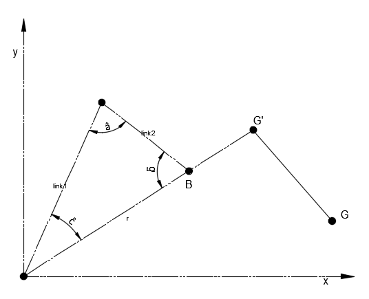
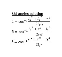
4- Triangle angles
Now we can draw a triangle, whom we know the three sides, which are the "r" length, link 1 length and link 2 length. Knowing the three sides we can find the angles values with SSS (side side side) formula.
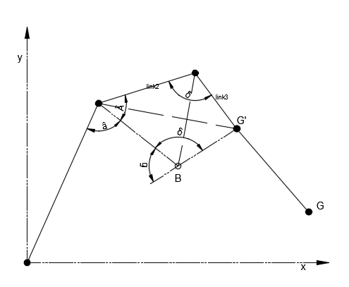
5-Deltoid angles
After that we have to find the last angles, and drawing a deltoid we can find the last one.
The deltoid is composed by two equal traingles, which we know two sides (link 2 and link 3) and the adiacent angle "delta". So calculating the diagonal length, we can calculate the A angle and we will complete the second joint angle.
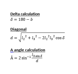
6-Find joint angles
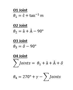
For translate our angles in a servo value we have to subtract and sum our angles.
- For Θ1 we add to "c^" angle the angle of the slope.
- For Θ2 we add "a^" angle and the A^ angle and subtract 90° for find the angle between the perpendicular to the link1 and the link2.
- Θ3 Is the subtraction of 90° to the delta angle.
- Θ4 is the subtraction of the sum of angles and "gamma" angle to 270°.
7-Servo convert
Now we have to write the angle Θ2 and Θ4 directly on the servo2 and 4, while for servo 1 and 3 we have to subtract the calculated angle to 180°, because of the opposite orientation of the servo.
Using this algorithm we can move the arm modifying the x, y and Grip angle values. So the arm create a vertical cartesian plane, but for now haven't a 3D coordinate space, so the Z axis is the rotation of the base servo.
SHOWING VIDEO
EXPANDED TECHNICAL DETAILS
4-Axis Kinematic Positioning
Bracc.ino is a desktop robotic arm designed for educational pick-and-place tasks.
- Servo Motor Array: Controls 4 MG996R or SG90 servos representing the Waist, Shoulder, Elbow, and Gripper.
- Potentiometer Control: Includes a "Teaching Mode" where the user moves 4 physical potentiometers. The Arduino maps these positions to the servos in real-time.
Structural Integrity
- Build Material: Typically 3D printed or laser-cut acrylic. The code includes "Speed Ramping" logic to prevent the servos from jerking, which protects the physical joints and ensures smooth, organic-looking movement.