Introduction & Materials I Used
Because I've been pretty intrigued by DACs and how they really work, I wanted to go ahead a build a simple implementation of it! A DAC is a system which converts a digital signal to an analog signal. If you want to know more about DACs and their applications, I've talked a bit more about that here.We are going to be designing a Digital to Analog system by building a circuit called an R-2R ladder. This circuit converts high/low voltage outputs (binary weights - with 1 referring to 5V and 0 referring to 0V) to an analog voltage (such as 4.6777). It accomplishes this through circuit analysis and voltage division.
About the Arduino UNO
Arduino is an open-source hardware platform, where you can program a microcontroller board to read in inputs, light up an LED when you push a button, or even to run a motor for a robot! The microcontroller is part of the Arduino board, and to feed it a set of instructions you need to use the Arduino programming language and its Integrated Development Environment, or its Web Editor. I’ve been so drawn into Arduino lately, especially because it opens up so many possibilities when it comes to projects, and it is easy to use and learn as well! This actually marks my second project with this board, so I’m kind of a newbie, but I LOVE IT!!! The board that I’ll be working with is called an Arduino UNO board.

Some of the main parts of this board are the Digital Pins. The Digital pins can serve as output or input pins. When used as output pins, they can act as power/voltage sources. When used as input pins, they take in signals as digital input! We will be using these pins to build our digital to analog converter, since we will need digital inputs to convert them into continuous analog form!!Another important part of the UNO board is the TX/RX LEDs. These LEDs indicate whether the UNO is transmitting (TX) or receiving (RX) data. When it's transmitting data, the TX LED blinks and when it's receiving data the RX LED blinks.
How it works
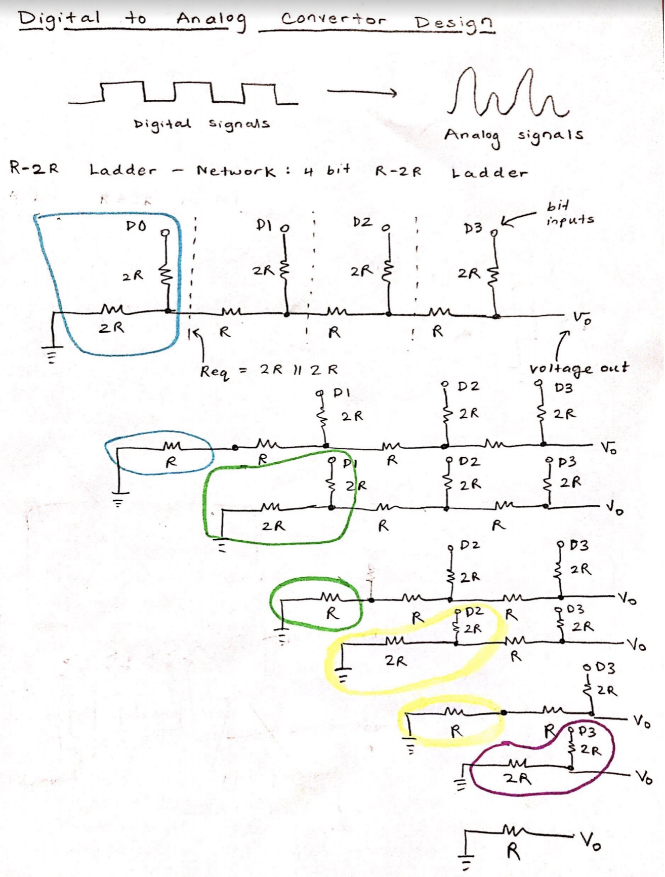
The circuit drawing above describes the R-2R ladder circuit. The configuration of this circuit resembles a ladder; 3 R resistors are all in horizontally faced as 4 2R resistors are placed vertically, in between the R resistors. The circles highlighted in color represent two resistors which are in parallel. 2 2R resistors in parallel result in an R resistor equivalent, since, by parallel resistor calculations, 1/2R + 1/2R = 2/2R, inverse is 2R/2 = R.
So with this circuit, we can simplify the resistors in the blue circle to just R. We can then add the two R's in series, and the equivalent resistance once again evaluates to 2R (just like the original circuit).
- This calculation gradually continues (as you can see from the highlighted circles appearing over and over again) until we are left with an output resistance or R, with Vout, being the output voltage (what we want). This goes back to the point where I mentioned about it being easy to calculate -- the output resistance is always R regardless of the number of bits, which is why the ladder configuration is very efficient.
- I decided to go for a 4-bit DAC (just like the one shown above), meaning our system will take in 4 bits (the binary weights) through 4 digital input pins (D2, D3, D4, D5) on the board. The DAC system then outputs the analog voltage and we will be outputting this into the Analog pin (A0) of our board. I used the 1Kohm resistors for R and 2Kohm resistors for 2R.
- The best thing about the resistor ladder circuit is that it's implementation is very self-explanatory. You place the resistors exactly how its indicated in the diagram! The 2R resistors are placed in parallel (one 2R to the left is connected to ground), and the R resistors are horizontally connected. This configuration ensures that the output resistance is R, and that the Vout calculates to an analog voltage. When I set 1's into every Digital pin, the output analog voltage was 4.68. Ideally, it should be close to 5, but this is because of the accuracy of our DAC. The more bits we have, the more close or accurate the results will be!! I feel like that was something I could have improved on, definitely by scaling the DAC and adding more digital pins as binary weights.
Physics of the Digital Barrier: 4-Bit DAC
An Arduino Uno has no true analog outputs. `analogWrite()` does NOT magically change the pin voltage to 3V; it just violently flickers 5V on and off extremely fast (PWM), which is useless for sensitive audio or radio processors! The 4-Bit Digital to Analog Converter (DAC) project forces you to build the "Analog" circuitry completely externally! You use raw C++ binary arrays to push massive voltages through a cascading wall of custom-soldered physical resistors.
Constructing the R-2R Ladder Topology
A DAC works by splitting physical electricity.
- A 4-bit system means we need exactly 4 Digital Arduino Pins (e.g., `D8, D9, D10, D11` or `D2, D3, D4, D5` as used in the original circuit).
- We arrange an enormous mathematical chain of Resistors on the breadboard.
- You need exactly two values of resistors (`R` and `2R`): e.g., 1K Ohm and 2K Ohm.
- The resistors are built into a "Ladder" formation, as shown in the circuit diagram above. The massive physics law here is voltage splitting. The most significant pin provides `2.5V` to the ultimate output. The next provides `1.25V`, then `0.625V`, and so on.
Synthesizing the Raw Output Matrix
The programmer controls exactly 16 different voltage steps (from `0b0000` to `0b1111`)!
- If the Arduino writes: `0000` = Output is a perfectly flat `0.0V`.
- If the Arduino writes: `1000` (Only the most significant pin is HIGH) = Output is exactly `2.5V`.
- If the Arduino writes: `1111` (All 4 Pins HIGH!) = Output hits maximum `5.0V`.
- The Execution Trap: You cannot use four slow `digitalWrite()` commands. It will create jagged, terrifying electrical spikes while the processor goes pin by pin.
- You must use raw bitmasking on the ATmega core registers! For example: `PORTB = (PORTB & 0xF0) | 0x05;` (This instantly fires pins to represent the decimal `5` perfectly across all the resistor grids in a singular clock cycle!).
Synthesizer Electronic Requisites
- Arduino Uno/Nano (For direct `PORTB` hardware register hacking!).
- At least Eight High-Precision Resistors! (e.g., Four 10k resistors and Four 20k resistors. The physics will fail completely if the tolerances are sloppy +/- 10%!).
- A Digital Multimeter (Absolutely critical for directly measuring the end output wire to prove you have created a perfect `2.5V` signal without using PWM!).
Procedure
There are actually multiple ways to build a digital to analog converter, but implementing a circuit called R-2R ladder is a popular and an effective method. The R-2Rladder circuit is a configuration of resistors in a "ladder like" format, which take in binary weights (bits) as inputs and convert them to an analog voltage. There are many advantages to implementing an R-2R ladder for a DAC.
Procedure is in this video!