Smart Motion Detection System using PIR Sensor and Arduino
In the current era where security systems are of paramount importance, building a basic alert system yourself not only helps save costs but also provides a good foundation for learning Embedded Systems. This project will demonstrate building a motion detector using a PIR (Passive Infrared) sensor with an Arduino board to activate an LED and a Buzzer when an intruder is detected.
Connections
Assembling this circuit is easy and straightforward, divided into 3 main parts as follows:
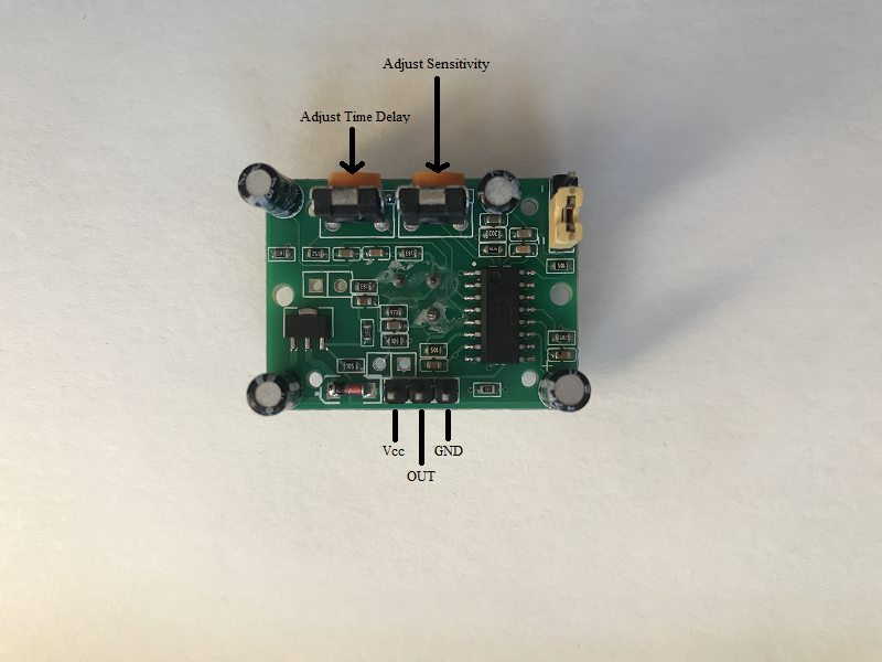
1). PIR to Arduino
- Connect the Vcc of PIR to 5V on Arduino
- Connect the GND of PIR to GND on Arduino
- Connect the OUTPUT pin of PIR to Digital pin D3 on Arduino
2). Buzzer to Arduino
- Connect one pin of buzzer to digital pin D8 on Arduino
- Connect other pin of buzzer to GND on Arduino
3). LED to Arduino
- Connect the LED positive to Digital pin D13 on Arduino through a resistor.
- Connect the LED negative to GND on Arduino.
Working Principle
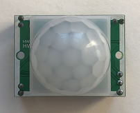
PIR sensor is a special type sensor which is usually used for security purposes. It detects the objects by reading the Infrared radiations emitted by the objects. Any object whose temperature is above absolute zero, emits radiation. This radiation is not visible to human eyes. The PIR sensor is designed to detect this Infrared radiation.
According to physics, all objects with a temperature above absolute zero always emit thermal radiation. Although invisible to the human eye, PIR sensors are designed to detect changes in these radiations, especially when a living creature moves across its Fresnel lens.
Analyzing the Source Code Logic
The program operates in a "State Monitoring" manner, with the following steps:
- Initialization: Configure pin D3 as
INPUTto receive the status from the PIR, and pins D8, D13 asOUTPUT. - Detection Loop: The Arduino will use the
digitalRead(3)command to check the status.- If motion is detected: The PIR will send a HIGH (5V) signal to pin D3. The program will then enter a condition to command
digitalWrite(13, HIGH)and produce sound through the Buzzer connected to pin D8. - If no motion is detected: The PIR will send a LOW (0V) signal. The program will immediately turn off the light and sound.
- If motion is detected: The PIR will send a HIGH (5V) signal to pin D3. The program will then enter a condition to command
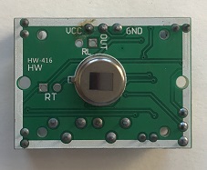
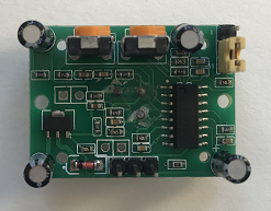
Customizing PIR Operating Modes
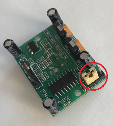
The PIR sensor has two modes. You can switch between these modes by interchanging the jumper behind the PIR sensor as shown in the images below.
a). Single trigger mode In this mode, when the sensor detects motion, the Output signal changes to HIGH and remains there for the set delay time. It then immediately changes to LOW, even if the object is still moving.
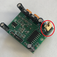
b). Repeatable trigger mode This mode is recommended for security applications. The Output signal remains HIGH as long as the sensor continuously detects motion. It will only start counting down to change to LOW when the object stops moving or leaves the detection range.
End Result
Once the circuit is assembled and the code is uploaded, the system will be ready to operate immediately (you may need to wait approximately 30-60 seconds for the PIR sensor to adjust to the environment or perform Calibration). When someone walks within the detection range, the LED will light up along with an alarm sound from the Buzzer.