Control an Arduino car with a phone.
This is my small contribution to the world of remote control Arduino cars. In this project, I built a car using Arduino ONE. The control SW for Arduino was written with the Arduino IDE and the code for the remote controller was written using Qt Creator. The phone app can be produced and downloaded to an Android phone using Qt Creator as well.
A small difference with other projects is that in this case the car can be told a speed in meters and the robots responds with its current speed in meters as well. Also, it tries to keep a given heading with the help of a compass.
The goal of this project is to be able to control the direction and speed of an Arduino based car from a mobile phone. The car should follow the commands received from the phone and avoid crashing with obstacles; whenever an element gets too close, the robot turns away from it, and continues with the previously programmed speed in the new direction.
Mounting the car
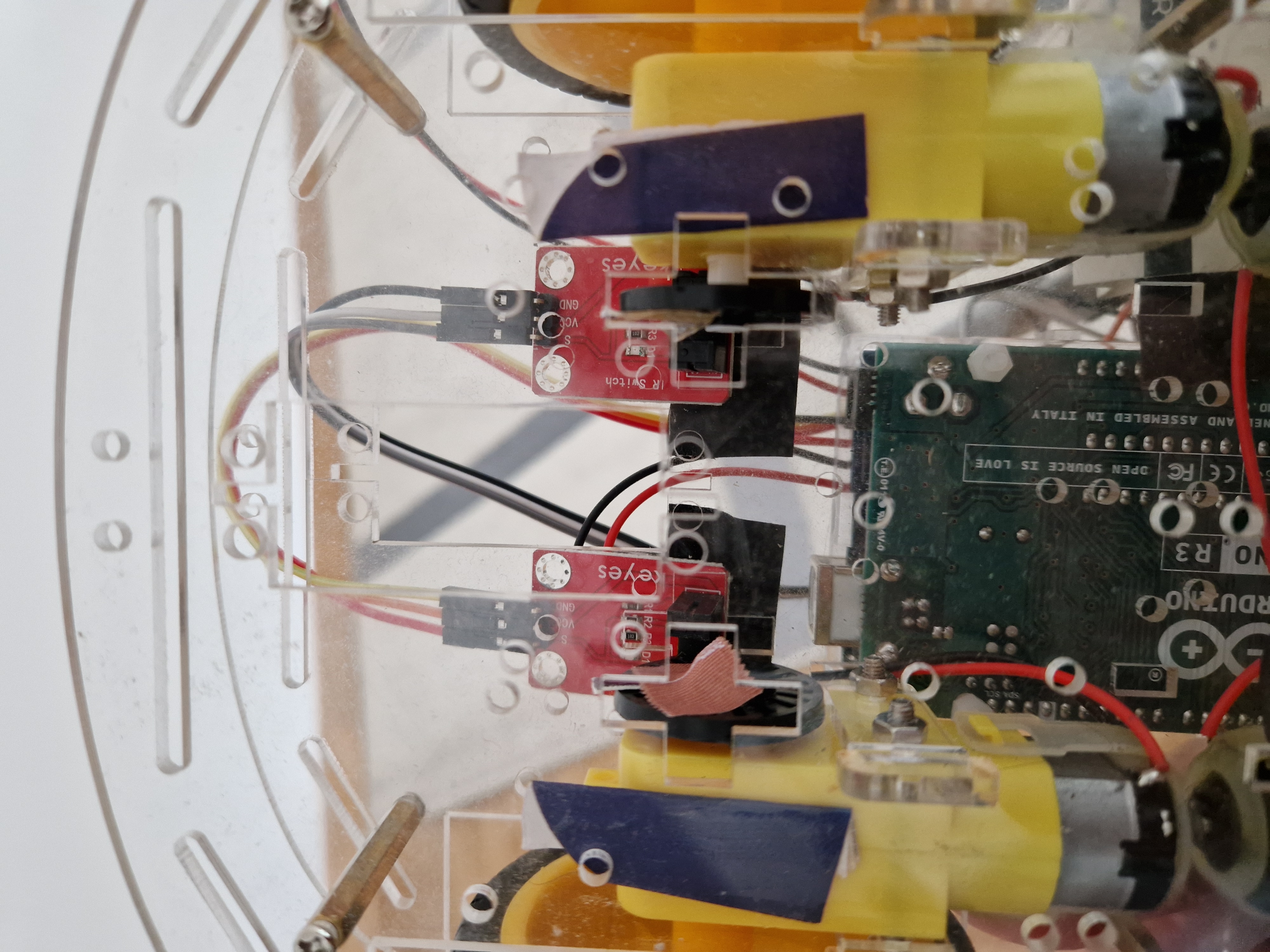
A commercial frame was used which supplies the wheels and motors. The full mounted and wired robot can be seen in the following images.
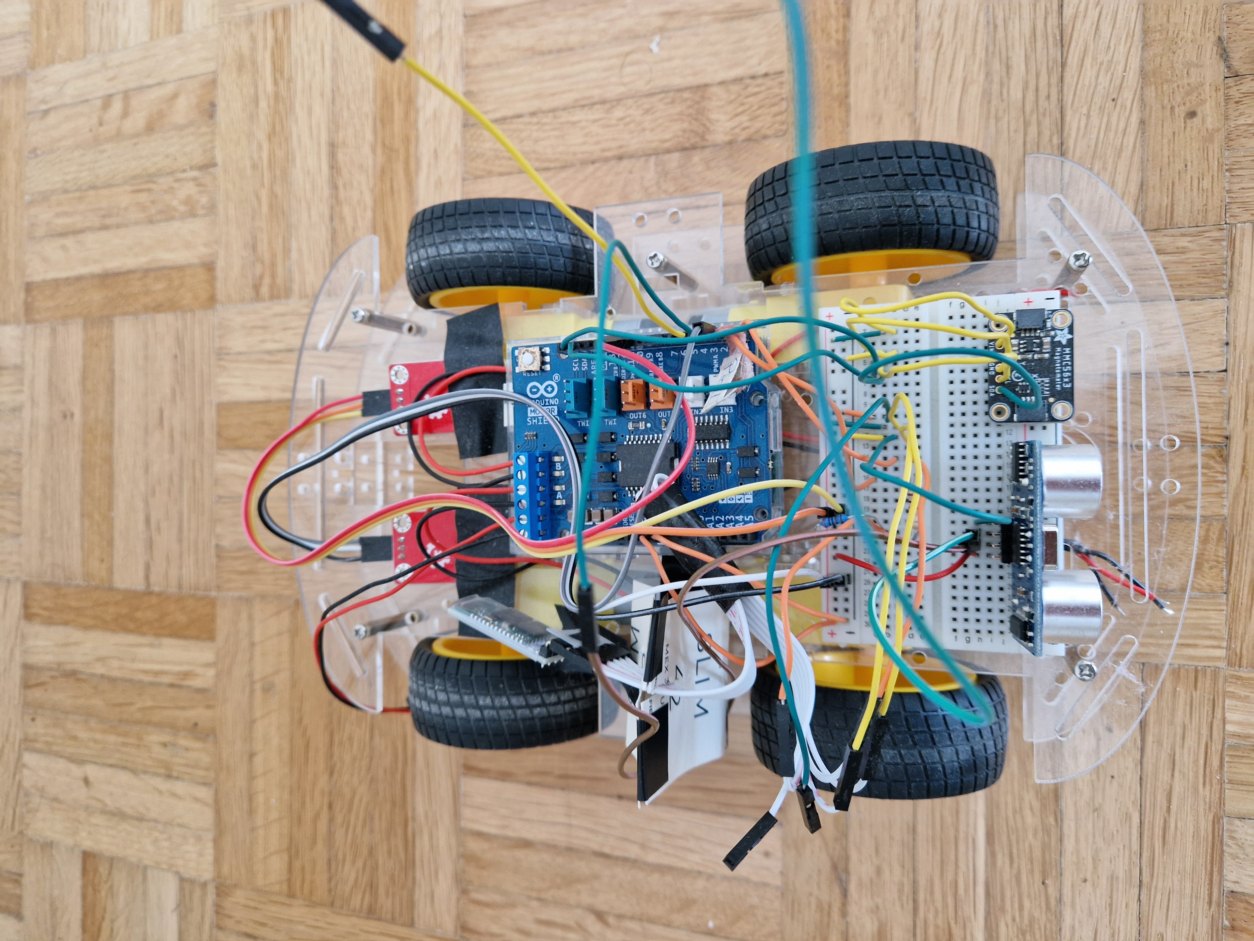
The hardware
A compass is used to asses the current direction follows the heading received from the phone. Speed is measured with the IR sensors as shown in the image above.
The ultrasound sensor allows to detect obstacles and avoid them and the communication with the phone (or computer) is done with a HC-05 Bluetooth module. A compass is used to keep the robot following a given heading.
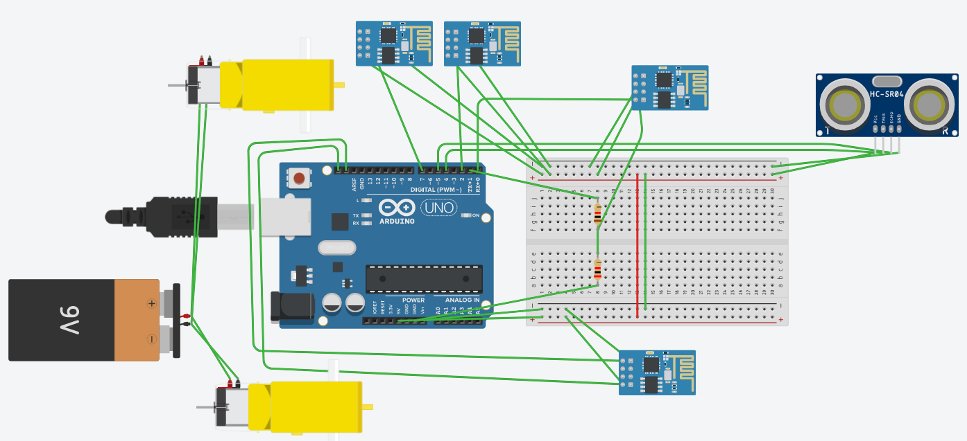
The following schemas show how all elements are connected with the Arduino.
EXPANDED TECHNICAL DETAILS
The Crash Detection Bluetooth Car merges two fundamental robotic theories: Human Teleoperation and Autonomous Override. You play the role of the driver utilizing an Android phone, but the Arduino plays the role of the Active Safety Engine.
Actuating the Heavy Current (L298N)
Because the Bluetooth module, sensors, and buzzer draw significant current, the motor driver board handles the harsh load. The L298N Module is installed between the batteries and the chassis motors, as shown in the wiring diagram above.
Serial String Dissection & Crash Logic
The phone app sends text commands constantly.
- The Reception: The HC-05 Bluetooth Receiver is wired into the `RX` and `TX` pins on the Arduino Uno.
- The Override Check: Before the Arduino reads the Bluetooth `RX` pin, it pings the HC-SR04 front ultrasound sensor.
- The Braking Logic:
- `if (distance > safe_threshold)`: Read Bluetooth and execute phone commands.
- `if (distance <= safe_threshold)`: The Arduino intercepts the command. It commands the motors to reverse briefly to bleed speed, then stops.
- The Beep: A piezo buzzer sounds an alarm, warning the user that the car has seized control to prevent a collision.
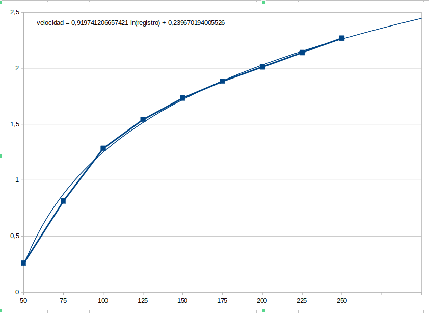
A set of experiments were made to approximate a conversion curve between meter per second and revolutions of the wheel depending on the PWM value set for each motor; this way, an estimate of the speed of each motor separately can be made.
The communication protocol
The car and the phone communicate with each other using a command – response protocol. Each command and respond is coded in frames that look like this:
< X p0 … pn >
where:
< → corresponds to the start of a frame
X → is a command or response code
p0 … pn → are parameters of a command or values of an answer
> → corresponds to the end of a frame
Once the application and the robot start, the application must connect to the robot, first opening a Bluetooth communication channel with it and then sending an activation command (<A>) which forces the robot to start collecting its own status information (speed and heading) and being ready for commands.
The car control
The code in the car implements behaviours to respond to different situations the robot may face; a behaviour implements specific actions of the robot in separated control code. The change between behaviours will happen when triggering conditions are detected. A state machine can illustrate this:
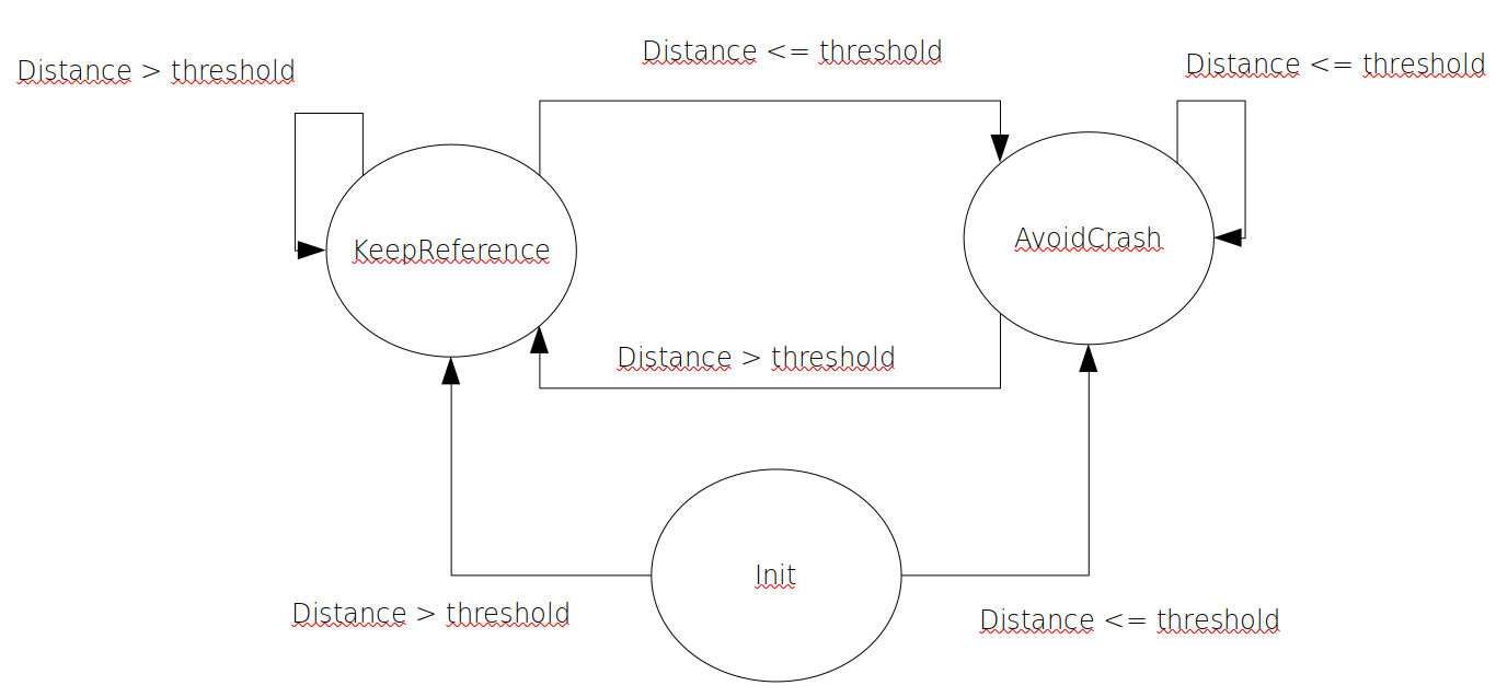
As shown in the state machine, there are 2 behaviours:
- keepReference. In this behaviour, the robot follows the reference given by the user. In the implementation, a PID was used without the derivative part to control the heading. In a follow-up project speed will also be controlled by using a PID.
- avoidCrash. The robot tries to avoid a crash autonomously in this case, in order to do that, the robot turns the wheels in a predefined speed in different directions to produce a counter-clockwise turn. In the mean time, the current heading is kept as reference.
The C++ application
I implemented the application in C++ using the Qt libraries and environment. The user interface is written using QML with C++ supporting classes.
The interface looks like this:
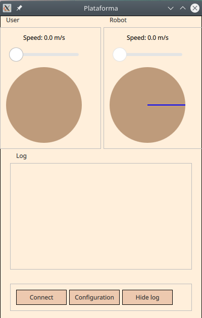
The group box on the top left side labeled “User” shows the information given by the user (desired speed and heading), the group box on the right (“Robot”) shows the information provided by the robot (its current speed and heading).
A text box (“Log”) shows the logs obtained from the robot or writen by the application as a help for debugging or just to have more accurate information of the current state of the communication. Last, the buttons on the bottom allow to connect / disconnect from the robot, show the configuration of the system or show / hide the text box with the logging information.
A video showing how the whole system works together can be found in this link: https://youtube.com/shorts/2sJkWdXCk8Y?feature=share
Requirements
- Arduino Uno/Nano: The safety computer.
- HC-05/06 Bluetooth Module: For interfacing with smartphone apps.
- HC-SR04 Ultrasonic Sensor: The active crash radar.
- 4WD or 2WD Acrylic Car Chassis Kit.
- L298N Dual H-Bridge Motor Driver.