The Inspiration
The Cleaner Bot was born from a desire to help with household chores. Specifically, the author was inspired by their mother, a caterer, who spent significant time cleaning her workspace. This project aims to automate that process, providing a robotic assistant that can handle light dusting and move around autonomously or via smartphone control.
Engineering & Design Choices
Building a functional cleaning robot requires balancing power consumption, weight, and autonomous navigation. In this version, several interesting design choices were made:
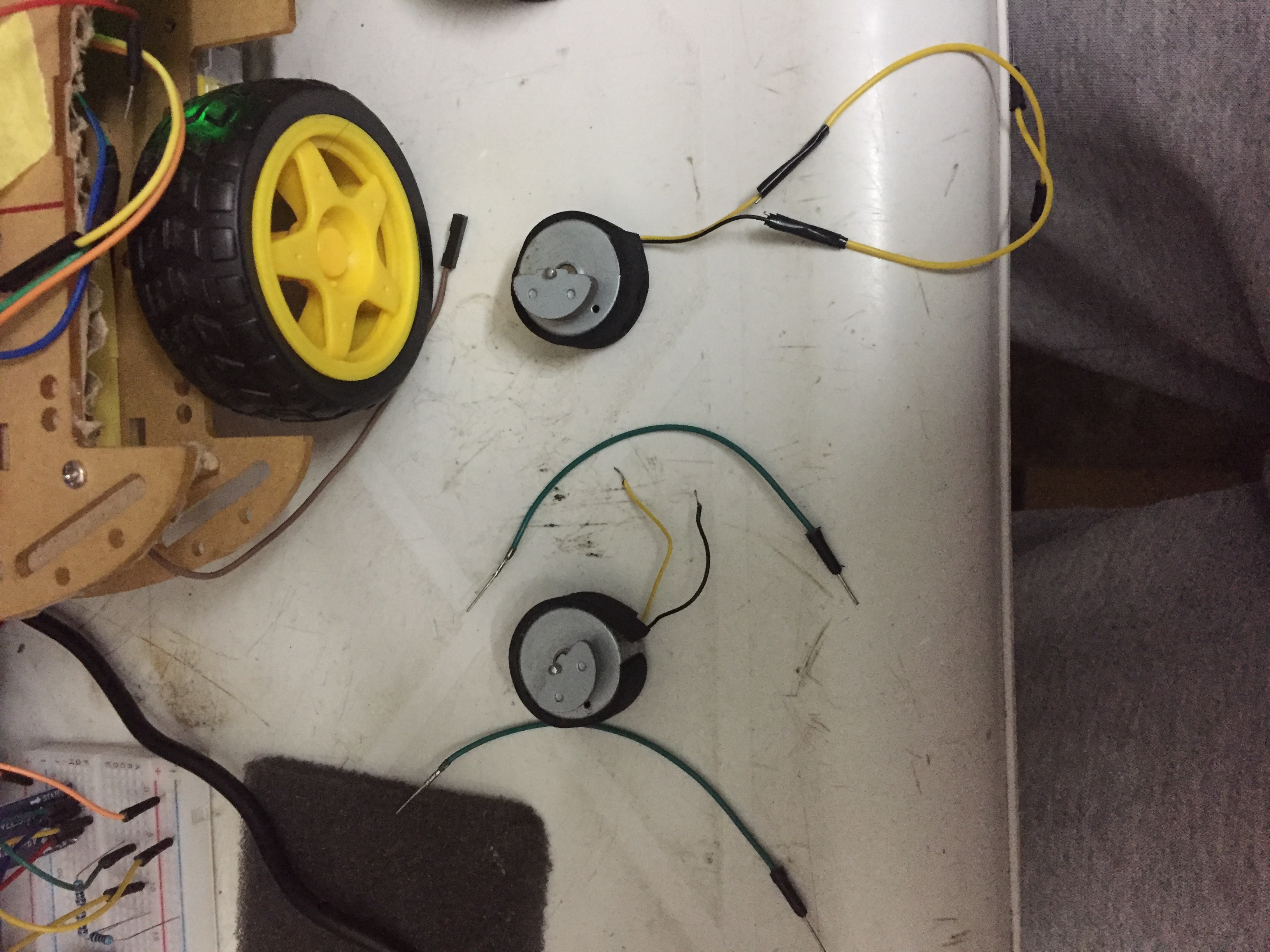
- Repurposed Hardware: To keep costs low, the author extracted DC motors from an old PS3 controller. While these motors are designed for vibration/haptic feedback, they are capable actuators for a small robot chassis when coupled with the right drive logic.
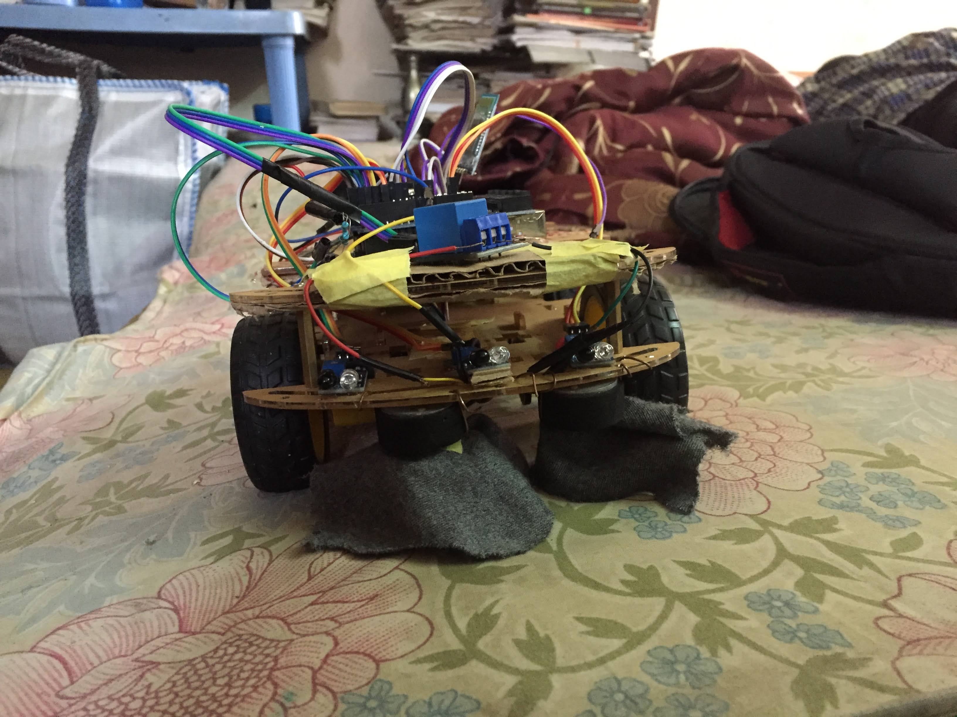
- Navigation Logic: The bot uses three Infrared (IR) sensors (Left, Center, and Right) to detect boundaries or obstacles. This allows the bot to "see" its environment and make decisions: if the left sensor detects a wall, it turns right; if all sensors detect an obstacle, it backs up and rotates.
- Drive System: Although the design initially considered an L298N motor driver, a Relay Module was used in some configurations for simplicity and efficient switching of higher current to the cleaning mechanism.
- Wireless Control: An HC-05 Bluetooth Module is integrated to allow manual overrides via a custom app built in MIT App Inventor 2. This enables "voice control" by using the smartphone's voice recognition to send serial commands like "start cleaning" to the Arduino.
Component Breakdown
- Arduino UNO: The brain of the operation, coordinating sensor inputs and motor outputs.
- HC-05 Bluetooth Module: Facilitates communication between the robot and a smartphone.
- IR Sensors (3x): Essential for autonomous obstacle avoidance.
- Relay Module: Used to trigger the high-speed cleaning motor.
- 18650 Li-ion Batteries (3x): Provides the high-current source required for sustained cleaning operations.
Understanding the Code Logic
The firmware is designed around a state-switching mechanism. It listens for Serial messages:
- When it receives "start cleaning", it sets a flag and initiates the
moveBot()function. - In
moveBot(), the Arduino reads all three IR sensors (lftIr,ctrIr,rghIr). - The logic follows a priority system: if an obstacle is on the right, turn left. If multiple obstacles are detected, execute a
backMov()to reset position. - The cleaning motor (connected to pin
rly) is activated whenever theswtchflag is high.
Construction Steps
- Chassis Assembly: Mount the recycled DC motors to a lightweight car kit chassis.
- Circuit Wiring: Connect the IR sensors to digital pins 12, 4, and 3. Set up the relay on digital pin 2.
- App Setup: Import the .aia file into MIT App Inventor 2 to create the voice-command interface.
- Calibration: Test the threshold of the IR sensors to ensure they correctly identify walls and dark surfaces.