The MKR MotorCarrier is a versatile booster for interfacing stepper motors. While it suggests stepper support, we investigate the real-world 'booster' interface needed to drive the 28BYJ-48 in both unipolar and bipolar fashions with surgically precise H-bridge control.
I use the popular stepper motor 28BYJ-48. It is widely available, and usually comes with an ULN2003 based driver board. That driver board will not be used here. The 28BYJ-48 is a 2-phase, unipolar motor. One phase is between blue and yellow, and the other is between the purple and orange wires. Each phase has a common center tap (red), which bifurcate a phase in two coils.
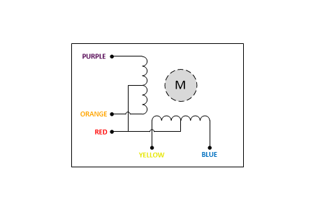
See the end of this project description for using this stepper in bipolar fashion.
The activation sequence used to drive the stepper here is the so called half-step mode:
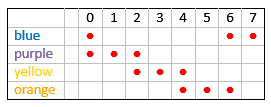
There are other modes, like wave-drive and full-step-drive, but they are not covered here. There are plenty of examples around, but they are not essential for this explanation. The activation sequence shown must be interpreted as follows: when the common center tap is connected to +VM, than an activation means a LOW on the to be activated coil. Or, with the common center tap connected to GND the activation needs a HIGH.
Engineering the Connection: The +VM Challenge
Connecting the common center tap to +VM is not trivial. While GND connections are available with the screw terminals on both sides of the MKR MotorCarrier board, there is not something like that for +VM.
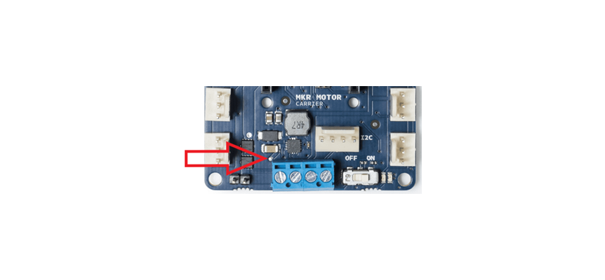
It’s possible to get +VM through the via (an electrical connection between board layers) as shown. It requires precision soldering. It is not advisable to shunt +VM directly from the power supply or from the battery. Then, when the power switch is off, there still remains power on the output stages of the drivers.
The power supply needed must deliver at least 6.5V, in accordance with the specification of the MKR MotorCarrier. Each coil of a phase measures 20Ω. Two coils can be active together so the power supply must be capable of delivering .65A.
An warning applies here: The 28BYJ-48 stepper motor is intended for 5V operation, but with a 7V supply I use there was never a problem.
The half step mode angle of the motor is 5.625°. It is geared down by a factor of 63.68395, so at the shaft it becomes 0.088326807617932°, meaning 4075.7728 steps for a full circle, to be precise.
The 28BYJ-48 Anatomy: Unipolar vs. Bipolar
On the MKR MotorCarrier there are 2 options to drive motors. One by means of the MC33926 drivers (the outputs M3±/M4±) and one by means of the DRV8871 drivers (the outputs M1±/M2±). There is theoretically a third possibility, via the LSF0108 level translator. However, this device is not capable to deliver enough current, at least not for the 28BYJ-48 stepper.
Both drivers incorporate a H-bridge output structure, here depicted with one phase of the stepper motor between outputs OUT1 and OUT2.
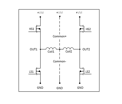
First we investigate the feasibility of this configuration with the MC33926 (Cn± denotes the common tap, either connected to +VM or GND). The MC33926 is directly controllable by the host, by means of the D2, D3, D4 and D5 pins. Neither the MotorCarrier's onboard SAMD11, nor the library is needed.
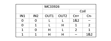
Both sides of a phase (1&2) active must be avoided according to the activation sequence presented, so with common+ all inputs 0, and with common- all inputs 1 must be avoided.
A problem presents itself here. The second the MKR 1010 WiFi is booting after a power up or a reset, its I/O’s are undefined and so are the MC33926 inputs. Disconnected inputs on the MC33926 cause high outputs (not shown here). In case of Cn- this leads to the undesirable condition. This flaw of the CarrierBoard can be overcome by applying 10kΩ pull-down resistors to the D2, D3, D4, D5 pins of the host’s headers.
If no pull-downs are provided, connecting the common tap to +VM is the only option, at least for documented operation.
Here is the truth table for a setup with the DRV8871. Again, Cn± means common tap connected to motor voltage +VM or GND. Z means a tri-state output condition.
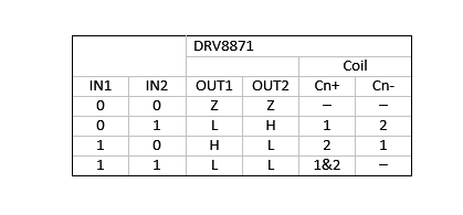
When using Cn+, the inputs IN1=1 and IN2=1 must be avoided. Then, if that can be guaranteed everything is OK.
In order to control the DRV8871 we need the onboard SAMD11 and thus the corresponding library. Mimicking 0’s and 1’s at the input is by employ the library’s setDuty() call, in particular setDuty(0), setDuty(100) and setDuty(-100).
Software Integration and Optimization
The project offers two control paths:
- Hardware Direct Steer: Using the MC33926 drivers (M3/M4 outputs). This allows the host MKR board to control the motor directly with sub-microsecond latency, bypassing the onboard SAMD11 co-processor for maximum speed.
- Library-Based Control: Using the DRV8871 drivers (M1/M2 outputs) via the SAMD11 co-processor and I2C commands. While convenient, this method introduces slight latencies (~9.8ms per call) that are better suited for slower, steady-state positioning rather than high-speed robotics.
There are some firmware issues when using the onboard SAMD11. The MotorCarrier isn’t connected with the common manual reset as available on the MKR 1010 WiFi. I experienced sporadic software crashes when using the manual reset. My guess is that while the MKR 1010 WiFi is resetted and booting, the SAMD11 firmware, in particular the I2C communication, just keeps running. I have concluded that ‘setters’ like the setDuty() never cause crashes, but ‘getters’ like getRaw() do.
The example sketches are pretty straightforward except for a few things that will be touched on here. The sector count SCTR can be any value up to and including 65535. A full circle counts about 4047 steps. The recommended frequency is 100Hz. This means a lag time LAG of 10000μs÷8steps=1250μs without considering the software overhead. When measuring, the overhead amounts ≈22μs when using the MC33926, and ≈2038μs with the library (SAMD11/DRV8871), in both measurements including calls to micros() and the serial monitor (2E6 Baud). So, with Stepper_on_M1_M2 the maximum speed is not feasible, and the delay with LAG is not necessary, strictly speaking.
In both sketches one must careful comment/uncomment the indicated statements, depending on the choice of the common+/common- mode.
Instead of the presented sketch Stepper_on_M3_M4, it is of course also possible to use the Arduino Stepper library. Because of the intermediary of the onboard SAMD11 this is not feasible with the DRV8871, i.e. M1±/M2±.
Thanks to the tri-state and H-bridge output capabilities of the DRV8871 it is possible to treat the 28BYJ-48 as a bipolar stepper, also. While in unipolar mode at a given moment only one part of a phase is energized, in bipolar mode the entire phase is used, with alternating GND/+VM on both ends. That swapping is possible with an H-bridge. What about the common center tap? In case both phases are activated the common points carries approximately ½VM, and that is acceptable. In the event that just one phase is activated, the other can be kept in tri-state, so there is no harm. You can drive the stepper, with disconnected center tap, also with sketch Stepper_on_M1_M2. It doesn’t matter if common+ or common- is selected.
The MC33926 has no tri-states. The central taps must be disconnected from each other to use this driver. Fortunately there are examples, how to cut the connection between the two central taps. After that, the 28BYJ-48 can be driven in bipolar mode by the MC33926. Again, it doesn’t matter if common+ or common- is selected in Stepper_on_M3_M4.
When running the stepper, unipolar either bipolar, by means of the library (and thus the onboard SAMD11), the motor runs less smoothly than without the library (i.e. by direct steering the MC33926). After some measuring it can be concluded that a call like setDuty() takes ≈9.8ms, largely due to the I2C-bus latency. This means that the settings inside an step takes a time comparable and so not neglectable with the working rate (100Hz) of the stepper. The sketch Bipolar_on_M1_M2 optimizes the time busy within the steps a little bit.
Whether you're building a precision laboratory slide or a high-torque robotic limb, this project serves as a definitive guide to expanding the capabilities of your MKR Motor Carrier hardware.