title: Controlling 8x8 LED Matrix with Shift Registers and Low-level Performance Optimization Techniques
When I first stepped into the world of Arduino with a basic Starter Kit, after grasping the fundamental logic, I decided it was time to create a project of my own.
My starting point was the desire to build a Sound Spectrum Analyzer to display audio frequencies via an LED Matrix. However, during the design phase, I encountered three significant engineering challenges:
- Pin Optimization: How can I control a large number of LEDs (64 individual LEDs) without consuming all of Arduino's pins?
- Performance: The display needs to be fast enough to leave sufficient CPU Cycles for Arduino to process the FFT algorithm for sound analysis.
- Power Management: How to control current to prevent system overload.
The project I'm sharing is the result of solving the first two problems, which serve as a crucial foundation before reaching a complete sound analyzer. This involves controlling an 8x8 LED Matrix using only two Shift Registers and minimal pins.
System Concept and Operation (Hardware Architecture)
The core of this project is the use of two 74HC595 Shift Registers working in conjunction with Multiplexing techniques.
- VCC Register (Anodes): The first one sends a positive signal (High) to the Anode pin of each column.
- GND Register (Cathodes): The second one acts as a ground (Low) for the Cathode pin of each row.

Note: The diagram above may have some reversed polarities in certain points, but the correct engineering principle for this project is:
- Connect the positive pin (Anode) of LEDs in the same column to the VCC Register.
- Connect the negative pin (Cathode) of LEDs in the same row to the GND Register.
Performance Optimization with SPI and Direct Port Access
To achieve maximum speed, I did not use Arduino's standard shiftOut() or digitalWrite() functions because these have high overhead. Instead, I opted for methods commonly used by embedded systems engineers:
- Hardware SPI: Utilizes the internal SPI module of the ATMega2560 chip (MOSI and SCK pins) to send data to the Shift Register at MHz-level speeds.
- Direct Port Access: Uses
SETandCLRcommands via thePORTEregister to control the Latch pins (pins 2 and 3 of Mega 2560), which is tens of times faster thandigitalWrite.
void PutColumnVCC(unsigned char col) {
  CLR(PORTE, pe_vccs_latch); // Pull Latch pin Low with Direct Port Access
  SPI.transfer(col);         // Send data via Hardware SPI
  SET(PORTE, pe_vccs_latch); // Pull Latch pin High to display output
}
Rendering Logic
To display images on an 8x8 Matrix, we cannot turn on all LEDs simultaneously, as this would draw too much current and prevent control over the image sequence. Therefore, we employ Row Scanning (scanning row by row) using the phenomenon of Persistence of Vision (POV).
In my code, I opted for Loop Unrolling in the Render() function to reduce computational load within the for loop:
// Example of row-by-row scanning logic
PutRowGND(0xFE); // Activate row 1 (B11111110 - Active Low)
for (int col = 0; col < 8; col ++) {
  int reg = 1 << col;
  PutColumnVCC((unsigned char)(LEDS[0] & reg)); // Send column data for row 0
}
PutColumnVCC(0); // Clear column values to prevent "Ghosting"
Image data is stored in an unsigned char LEDS[8] array, where 1 Byte represents 1 row, and each Bit within that Byte represents an individual LED in that row (Column).
Non-blocking Time Management
A common problem for beginners is using delay(), which causes LED scanning to halt and results in flickering. In this project, I use a counter variable to create a Software Timer-based delay system, allowing row scanning to operate continuously while the program changes image frames according to the defined scroll_speed.
Features and Interaction (User Interface)
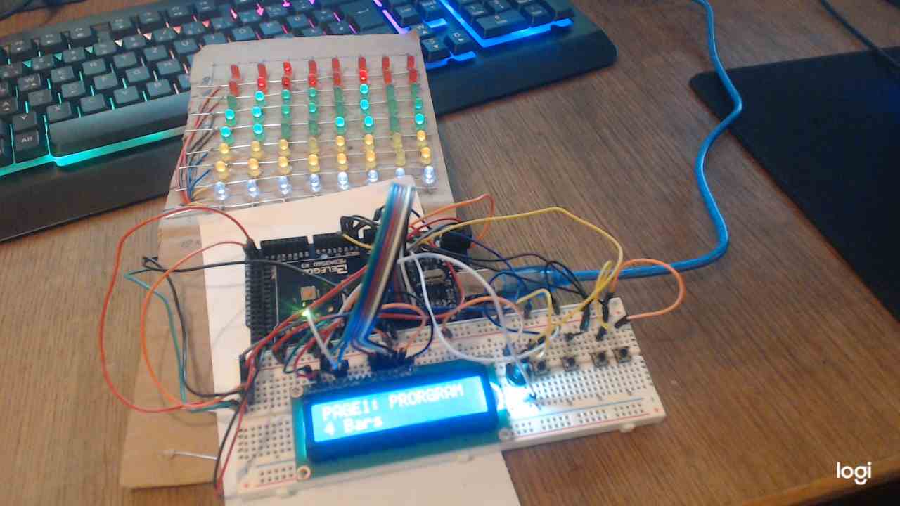
I added a 16x2 LCD screen and four buttons to create a functional menu system:
- Page 1 (Program Selection): Select from over 20 display patterns (e.g., Wave, Heart, Alphabet).
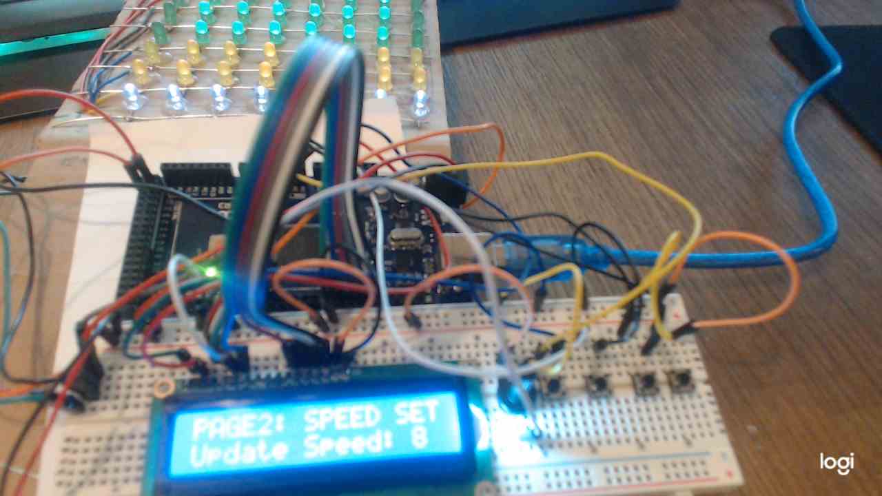
- Page 2 (Speed Set): Adjust the animation speed.
- Page 3 (Direction): Toggle scanning direction to test Hardware performance.
Engineering Summary
Using two Shift Registers to control 64 LEDs with this technique offers clear advantages:
- Low Power Consumption: Because LEDs are lit one by one (or one row at a very fast scan rate), it consumes very little current, almost equivalent to lighting a single LED.
- Pin Efficiency: We use only 4 main pins (2 Latch pins + 2 SPI pins), leaving plenty of PWM and Analog pins available for other sensors.
- High Speed: The use of Hardware SPI and Direct Port Access makes this system readily expandable into a Spectrum Analyzer that requires real-time processing.
Although the circuit on the Breadboard might look a bit messy, this is a crucial first step in understanding the register-level operation of microcontrollers, which is at the heart of becoming a professional embedded systems engineer!