Physical Movement: Knob-Controlled Servos
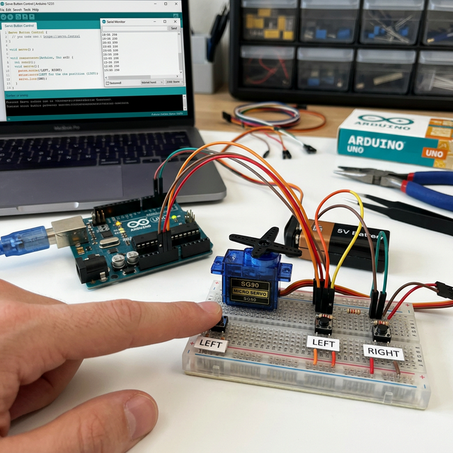
The Potentiometer-Controlled Servo is one of the most satisfying beginner projects. It creates a direct physical link between your hand’s movement and the motor’s response, making it the perfect foundation for camera gimbals and robotic steering.
How It Works: Pulse Width Modulation
- The Dial: You turn the 10k potentiometer. The Arduino reads a value from 0 to 1023.
- The Translation: The code uses the
map()function to convert that 0-1023 value into an angle from 0 to 180 degrees. - The Pulse: The Arduino sends a specific electrical pulse (PWM) to the servo.
- The Movement: The internal electronics of the servo interpret that pulse and move the motor shaft to the exact angle corresponding to your knob's position.
Hardware Components
- Arduino Uno/Nano: The PWM signal generator.
- SG90 Micro Servo: The output device.
- 10k-ohm Potentiometer: The analog input device.
- Breadboard and Jumper Wires.
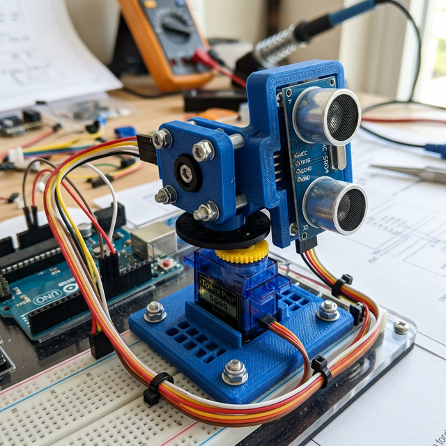
Why This Project?
This setup is the core of Master-Slave systems used in industrial robotics and surgical arms. By mastering the coordination between an analog input and a servo output, you're ready to build more complex joints for humanoid robots or pan-tilt mounts for tracking cameras.