In this tutorial we will see how to create a device to control lights by voice commands, with a module from geeetech.
In this tutorial we will see how to create a device to control lights by voice commands, with a module from geeetech, designed for this purpose. We will see how to assemble this device on a PCB manufactured by PCBWay. We will analyze the hexadecimal commands for its configuration, and the source code. Finally, we will test its operation.
Electronic components
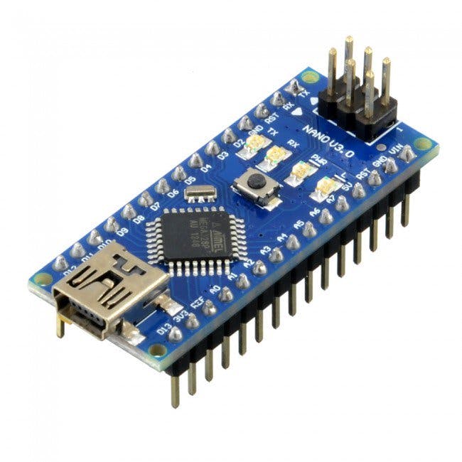
Arduino Nano
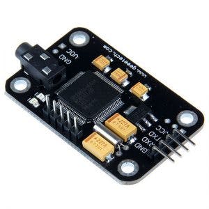
Voice recognition module
Voice recognition module command
0x00–>Enters waiting mode for some command
0x01 –>Delete instructions from group 1
0x02 –>Delete instructions from group 2
0x03 –>Delete instructions from group 3
0x04–>Delete instructions from all 3 groups
0x11–>Start recording group 1 instructions
0x12–>Start recording group 2 instructions
0x13–>Start recording group 3 instructions
0x21–>Import group 1 for using voice commands
0x22–>Import group 2 for using voice commands
0x23–>Import group 3 for using voice commands
0x24–>Check the recorded groups
0x31–>Change speed to 2400 bps
0x32–>Change speed to 4800 bps
0x33–>Change speed to 9600 bps
0x34–>Change speed to 19200 bps
0x35–>Change speed to 38400bps
0x36–>Switch to common mode
0x37–>Switch to compact mode
0xbb–>Module version information
Parameters
Voltage: 4.5-5.5V
Current: <40mA
Digital interface: 5V TTL
Analog interface: 3.5mm mono-channel microphone jack + microphone pin interface
Size: 30mm x 47.5mm
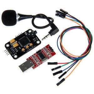
KIT
This kit consists of a voice recognition module, a USB serial module, cables and a microphone.
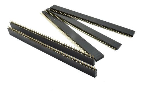
Male pins

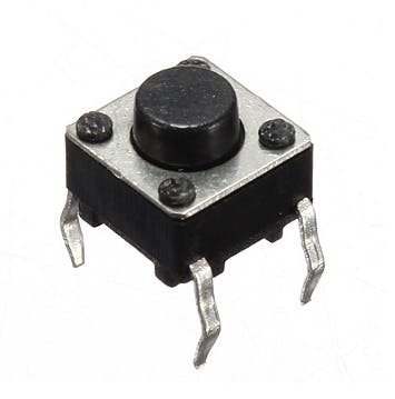
Eight Push Buttons
Female Pines
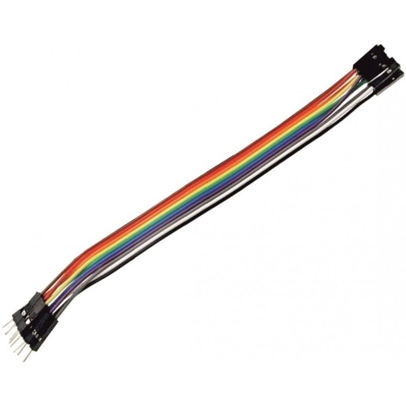
Dupont cables female male
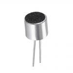
Electret microphone
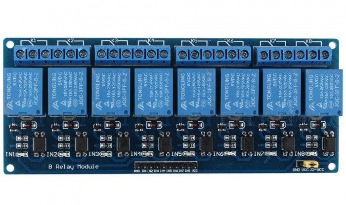
8 channel relay module
Characteristics
Allows you to control the on/off of high-power equipment (household appliances). Works perfectly with Arduino, Pic or any other digital system.
Within the wide variety of projects that we can carry out with Arduino, we may want to control high voltage or high amperage components, such as light bulbs or water pumps, which cannot be controlled directly with Arduino. In these cases it is necessary to use Relays, these devices allow controlling high voltage loads with a small signal.
The module has 8 high quality Relays, capable of handling loads up to 250V/10A. Each channel has electrical isolation by means of an optocoupler and a status indicator LED. Its design facilitates work with Arduino, as well as with many other systems such as Raspberry Pi, ESP8266 (NodeMCU and Wemos), Teensy and Pic. This Relay module activates the normally open output (NO: Normally Open) when receiving a logical “0” (0 Volts) and deactivates the output with a logical “1” (5 Volts). For Arduino and Relay programming, it is recommended to use timers with the “millis()” function and thus not use the “delay” function that prevents the system from continuing to work while a relay is activated/deactivated.
Among the loads that can be handled are: light bulbs, luminaires, AC motors (220V), DC motors, solenoids, solenoid valves, water heaters and a wide variety of other actuators. It is recommended to make and verify the connections before powering the circuit, it is also good practice to protect the circuit inside a case.
Technical data
8 independent channels
8 1-pole 2-throw relays
The relay coil voltage is 5 VDC
LED indicator for each channel (lights up when the relay coil is active)
Current activated: the control circuit must provide a current of 15 to 20 mA
It can be controlled directly by logic circuits
Screw connection terminals (clamps)
Logic signal input terminals with 0.1″ male headers.
It can be controlled directly by logic circuits
Food and consumption
The easiest way to power this module is from Vcc and GND of the Arduino board, keeping the Jumper in place, so JD-Vcc = Vcc. This connection has two important limitations:
The electrical isolation provided by optocouplers is lost, increasing the possibility of damage to the Arduino if there is a problem with the relay loads.
The current consumed by the relay coils must be supplied by the Arduino board. Each coil consumes about 90 mA and the four together add up to 360 mA. If we add to this the consumption that other outputs can have, we are very close to the 500 mA that a USB port can supply. In this case the Arduino should be powered with an external source, which increases the current limit to 1 A (in the case of the Arduino UNO).
The safest way is to remove the jumper and power the relay board with two sources: the one from the Arduino board connected to Vcc and a second source, with the positive to JD-Vcc and the negative to GND, without being connected to the Arduino board. This connection has the following advantages:
There is complete isolation between the load and the Arduino.
All relay power is taken from the second source and not from the Arduino or the USB port.
Tickets
The inputs to the board can be connected directly to the digital outputs of the Arduino board. The only precaution to take into account is that when the Arduino is started by being powered up, the pins are automatically configured as inputs and it may happen that, for a very short period of time between the start-up and the correct configuration of these pins as outputs, the control inputs to the relay module remain in an undetermined state. This can be avoided by connecting a pull-up with a 10K resistor to Vcc on each input, which ensures a HIGH state during start-up.
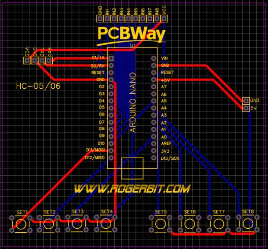
PCB
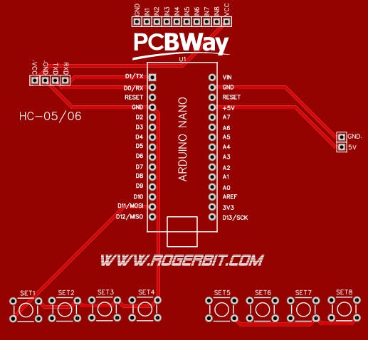
Download PCB –> https://rogerbit.com/wprb/wp-content/uploads/2021/09/control-de-luces-de-8-canales-por-bluetooth.zip
Circuit
System Architecture and Technical Details
This project demonstrates a local, offline approach to voice control. Unlike systems that rely on cloud servers (like Amazon Alexa or Google Assistant), this setup uses the raw processing power of your Android smartphone to perform speech-to-text offline, and then beams the resulting command string to the Arduino via a serial interface (or Bluetooth in an alternative configuration).
The Speech-to-Text Pipeline
You do not write the complex voice recognition software on the Arduino. The process is handled upstream:
- The App/Module: You use a dedicated voice recognition module (as shown in the component images above) or, in an alternative Bluetooth-based design, you could download an app like `AMR_Voice` (Arduino Voice Control) on your Android device.
- Command Capture: You speak a command, such as "Turn on the kitchen light."
- Processing & Transmission: The audio is parsed into text. With the dedicated module, it outputs a pre-defined command code. In a Bluetooth app scenario, the phone would transmit a pure text string like
*kitchen light on#via Bluetooth to a module like an HC-05.
Arduino Command Parsing
The Arduino, connected to the voice module via serial (or to a Bluetooth module), waits for incoming data. It uses a parsing routine to identify the start and end of a complete command. For a text-based system, it looks for delimiters like `*` (start character) and `#` (end character).
if (voiceCommand == "kitchen light on") {
  digitalWrite(Relay1, HIGH);
  Serial.println("Kitchen executed!");
} else if (voiceCommand == "all lights off") {
  digitalWrite(Relay1, LOW);
  digitalWrite(Relay2, LOW);
}
With the dedicated Geeetech module used in this project, the parsing is based on the hexadecimal command set listed earlier.
Adding Manual Overrides (Keys)
A robust smart home system must have a manual fallback. This is why the component list includes Push Buttons (Keys), as shown in the image above. These are wired in parallel with the logic of the voice commands. Whether the Arduino receives a valid voice command or detects a physical button press, it toggles the corresponding relay. This ensures the system remains functional even if you don't have your phone or if there is a issue with the voice module.
System Setup Summary
- Controller: Arduino Nano (as shown above).
- Voice Input: Geeetech Voice Recognition Module (primary method for this tutorial).
- Alternative Wireless Control: HC-05 or HC-06 Bluetooth Module (for a phone-based approach).
- Actuation: 8-Channel Relay Module (to safely handle mains voltage for lamps).
- Manual Control: Physical push buttons for manual override.
Source Code Overview
The serial port speed is set to 9600bps, which is the default speed for the voice recognition module.
With the commands:
Serial.write(0xAA);
Serial.write(0x37);
We send the serial command `AA 37` to switch the module to compact mode.
With the commands:
Serial.write(0xAA);
Serial.write(0x21);
We send the `AA 21` command to select the group to work on the module. Remember that there are 3 groups of 5 voice commands, but only one group can be active at a time.
The code also includes functions like color(255,102,0); which is called to pass PWM parameters to pins connected to dimmer switches, allowing for light intensity control alongside simple on/off commands.