Principle:
1. Button
Buttons are a common component used to control electronic devices. They are usually used as switches to connect or disconnect circuits. Although buttons come in a variety of sizes and shapes, the one used in this experiment will be a 12mm button as shown below.
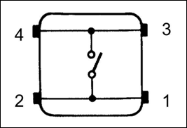
The button we used is a normally open type one. The two contacts of a button are in the off state under the normal conditions; only when the button is pressed they are closed.
The button jitter must happen in the process of using. The jitter waveform is as the flowing picture:
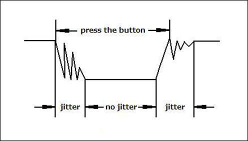
Each time you press the button, the Arduino will regard you have pressed the button many times due to the jitter of the button. You should deal with the jitter of buttons before using. You can eliminate the jitter through software programming. Besides, you can use a capacitor to solve the issue. Take the software method for example. First, detect whether the level of button interface is low level or high level. If it is low level, 5~10ms delay is needed. Then detect whether the level of button interface is low or high. If the signal is low, you can infer that the button is pressed once. You can also use a 0.1uF capacitor to avoid the jitter of buttons. The schematic diagram is as shown below:

Fundamental Input/Output Logic
A core educational project exploring the relationship between physical user input and digital state management.
- Software Debounce Implementation: Explains why a physical button press is "Dirty" (electrically noisy). The code uses a 50ms temporal filter to ensure a single press results in exactly one state change.
- Pull-up Resistor Topology: Utilizes the Arduino's internal
INPUT_PULLUPresistors, reducing the component count and ensuring the input pin is never left "Floating."
Interaction Modes
- Momentary vs. Toggle: Includes code examples for both a "Push-to-Light" mode and a "Latch" mode where the button act as a toggle switch.
2. Interrupt
Hardware interrupts were introduced as a way to reduce wasting the processor's valuable time in polling loops, waiting for external events. They may be implemented in hardware as a distinct system with control lines, or they may be integrated into the memory subsystem.
Key functions:
attachInterrupt(interrupt, ISR, mode) Specifies a named Interrupt Service Routine (ISR) to call when an interrupt occurs. Replaces any previous function that was attached to the interrupt. Most Arduino boards have two external interrupts: numbers 0 (on digital pin 2) and 1 (on digital pin 3).
Generally, an ISR should be as short and fast as possible. If your sketch uses multiple ISRs, only one can run at a time, other interrupts will be ignored (turned off) until the current one is finished. as delay() and millis() both rely on interrupts, they will not work while an ISR is running. delayMicroseconds(), which does not rely on interrupts, will work as expected.
Syntax:
attachInterrupt(pin, ISR, mode)
Parameters:
- pin: the pin number
- ISR: the ISR will be called when the interrupt occurs; this function must take no parameters and return nothing. This function is sometimes referred to as an interrupt service routine.
- mode: defines when the interrupt should be triggered. Four constants are predefined as valid values:
- LOW to trigger the interrupt whenever the pin is low,
- CHANGE to trigger the interrupt whenever the pin changes value
- RISING to trigger when the pin goes from low to high,
- FALLING for when the pin goes from high to low.
digitalRead() Reads the value from a specified digital pin, either HIGH or LOW.
Syntax:
digitalRead(pin)
Parameters:
- pin: the number of the digital pin you want to read (int)
Returns: HIGH or LOW
delayMicroseconds(us) Pauses the program for the amount of time (in microseconds) specified as parameter. There are a thousand microseconds in a millisecond, and a million microseconds in a second. Currently, the largest value that will produce an accurate delay is 16383. This could change in future Arduino releases. For delays longer than a few thousand microseconds, you should use delay() instead.
Syntax:
delayMicroseconds(us)
Parameters:
- us: the number of microseconds to pause (unsigned int)
Procedure: Step 1: Build the circuit. Step 2: Compile the program and upload to Arduino UNO board
Now press the button, and you can see the state of the LED will be toggled between ON and OFF.