Creating a MIDI pass-through recorder
If you've ever used audio software on the computer, you probably know that MIDI exists: a signalling protocol that allows controllers to control virtual instruments like synths. It's also the protocol used by real audio hardware to talk to each, and you can think of it as the language in which, rathar than communicating a fluctuating voltage signal or series of discrete sample values, devices talk about what is being done on them ("A4 got pressed", "F4 got released", "the mod wheel moved down", etc).
As such, there are two ways to record digital instruments (real or virtual): you can record the sound they're making, or you can record the MIDI events that cause them to make those sounds, and that's where things get interesting.
There are many, many ways to record audio, from microphones to line monitors to audio interfaces, on dedicated hardware, computers, phones, etc. etc., but there aren't all that many ways to record MIDI events. Essentially: unless you're running software that monitors MIDI events, there just isn't really any way to record MIDI. So I set out to change that: in the same way that you can just hook up an audio field recorder (like a Tascam DR-05) to sit between an audio-out on something that generates audio and an audio-in on something that should be listening to that audio, writing that to an SD card as .wav or .mp3 or the like, I built a MIDI "field recorder" that you plug in between your MIDI-out and some MIDI-in, indiscriminately recording every MIDI event that gets sent over the wire to an SD card as a .mid file.
You'd think this would be something that already exists as a product you can just buy (even if at probably quite the markup because it's made of "powder-coated extruded aluminium" with "audiophile quality" components, but still). Amazingly, it is not. There's just nothing.
So: if you want a MIDI recorder, you'll have to build one... and if you want to build one, this post might be useful to you!
The circuitry
To build this, we're going to basically build a standard "MIDI-In + MIDI-Thru" circuit using an Arduino, with an SD card module hooked up so we can save the data that comes flying by. To build everything, we'll need some special components:
- An Arduino SD card module (~$10 for a pack of five)
- Two female 5-pin DIN connectors (~$5 for a pack of ten)
- A 6N138 optocoupler (~$10 for a pack of ten)
- Optional: a DS3231-based RTC module
And of course, the bits that you'll get with pretty much any Arduino starter kit:
- An Arduino UNO R3 or equivalent board
- 3x 220 ohm resistors
- 1x 4.7k ohm resistor
- 2x 10k resistors
- A diode
- A piezo buzzer
- Two clicky pushy buttons
The MIDI part of our recorder
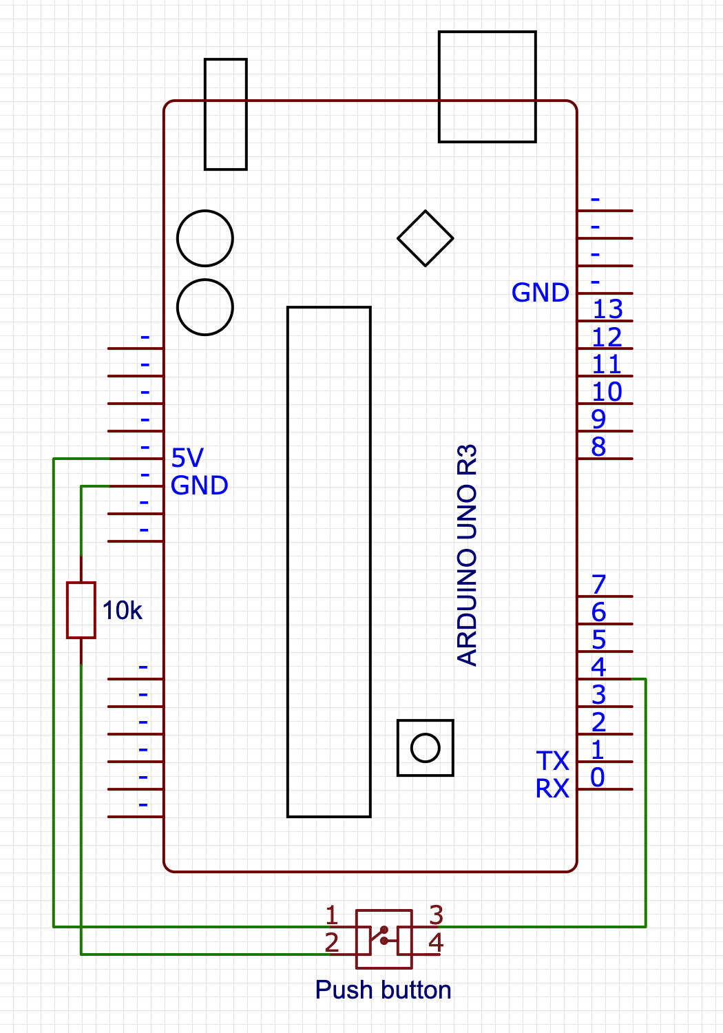
We set up MIDI-In on the Arduino RX<-0 pin, with MIDI-Thru tapping straight into signal that's getting sent to RX<-0, too. The only tricky bit about this is that MIDI signals are isolated from the rest of the circuitry via an optocoupler (which gets around ground loop problems by literally transmitting signals by running them through a LED, which emits the electrical signal as light, which then gets picked up by a phototransistor that turns the light back into an electrical signal). When placing and connecting the optocoupler, it is very important to make sure you know which pin is pin 1: it'll have a little mark next to it (typically a dot on the chip casing) to tell you that that side has pins 1 through 4 running top to bottom, and pins 5 through 8 on the other side running bottom to top. Also note that we're not using pins 1 and 4 for this circuit: only pins 2 and 3 are connected to the MIDI-In connector, and pins 5 through 8 are connected to the various arduino pins.

(I know, "Thru isn't a word!", but that's what the MIDI spec calls it, so English gets to take a back seat here...)
The SD part of our recorder
The SD card circuitry is literally just a matter of "connect the pins to the pins", with the only oddity being that the pins don't quite line up well enough to literally just stick the SD card module directly into the Arduino.
However, note that your SD card module may have a different pin layout so be sure to double-check before wiring things up!

Adding a MIDI marker button
In order to make it easier to find particularly "worth revisiting" parts of what got recorded, we add a button that connects to pin 4, that we can use to write MIDI markers into our file. There is barely anything to this circuit:
Adding a beep, for debugging
And finally, we're going to add a little piezo speaker and a button that we can press to turn on (or off) playing a note corresponding to a MIDI note getting played, mostly as the audio equivalent of visual debugging. There's barely any work here: we hook up the "speaker" between pin 8 and ground, and the button to pin 2. Beep, beep!

Optional: adding a Real Time Clock
Our last bit of circuitry is not required in the slightest, but it does improve usability quite a bit: a real-time clock using a DS3231 chip, which is a “fancy” RTC with some smart bits that keeps it accurate regardless of temperature changes. Connecting it is pretty straight forward, and uses some pins on the side of the Arduino we’ve not used yet, connecting the SDA (or “D”) pin to the A4 input, and the SCL (or “C”) pin to the A5 input. What will this get us? For one we the SD card library can make us of it to make sure files have a real file date, and secondly, it’ll allow us to write MIDI markers that are linked to dates and times, rather than being a simple sequence number. Both these things will make it easier to find past work more easily.

The Software
With the circuitry set up, let's start writing our program, focussing on dealing with each circuit in its own section
- Program basics
- Basic signal handling (MIDI library)
- Basic file writing (SD library)
- Saving MIDI markers
- Audio debugging (beep beep)
- Usability bonus: "clean restart" on idle
- Usability bonus 2: "fix the track length" script
Program basics
Our basic program will need to import the standard SD library, as well as the MIDI library (which you'll probably need to install first).
Note that if you don't want to "follow along" and instead you just want the code, you can copy-paste the code found over in midi-recorder.ino into the Arduino IDE.
#include <SD.h>
#include <MIDI.h>
MIDI_CREATE_DEFAULT_INSTANCE();
void setup() {
  // we'll put some more code here in the next sections
}
void loop() {
  // we'll put some more code here in the next sections
}
And we're done!
Of course this doesn't do anything yet, so let's add the rest of the code, too.
MIDI handling
For our MIDI handling, we'll need to set up listeners for MIDI events, and make sure to poll for that data during the program loop:
void setup() {
  MIDI.begin(MIDI_CHANNEL_OMNI);
  MIDI.setHandleNoteOn(handleNoteOn);
  MIDI.setHandleNoteOff(handleNoteOff);
  MIDI.setHandlePitchBend(handlePitchBend);
  MIDI.setHandleControlChange(handleControlChange);
}
void loop() {
  checkForMarker();
  setPlayState();
  updateFile();
  MIDI.read();
}
This sets up MIDI listening on all MIDI channels (there are sixteen of them, and we don't want to guess which channels are active), and reads out the MIDI data from RX<-0 - you may have noticed we don't explicitly set a baud rate: the MIDI spec only allows for 31, 250 bits per second, so the MIDI library automatically makes sure to set the correct polling rate for us.
You'll notice that loop() does four things: we'll only be looking at the MIDI reading in this section, with the next sections covering the other three steps.
For now, assuming that the first three function calls work (because they will, later =), that leaves implementing our MIDI event handling:
#define NOTE_OFF_EVENT 0x80
#define NOTE_ON_EVENT 0x90
#define CONTROL_CHANGE_EVENT 0xB0
#define PITCH_BEND_EVENT 0xE0
void handleNoteOff(byte channel, byte pitch, byte velocity) {
  writeToFile(NOTE_OFF_EVENT, pitch, velocity);
}
void handleNoteOn(byte channel, byte pitch, byte velocity) {
  writeToFile(NOTE_ON_EVENT, pitch, velocity);
}
void handleControlChange(byte channel, byte controller, byte value) {
  writeToFile(CONTROL_CHANGE_EVENT, controller, value);
}
void handlePitchBend(byte channel, int bend_value) {
  // First off, we need to "re-center" the bend value,
  // because in MIDI, the bend value is a positive value
  // in the range 0x0000-0x3FFF with 0x2000 considered
  // the "neutral" mid point, whereas the MIDI library
  // gives us a signed integer value that uses 0 as its
  // midpoint and negative numbers to signify "down".
  bend_value += 0x2000;
  // Then, per the MIDI spec, we need to encode the 14 bit
  // bend value as two 7-bit bytes, where the first byte
  // contains the lowest 7 bits of our bend value, and second
  // byte contains the highest 7 bits of our bend value:
  byte lowBits = (byte) (bend_value & 0x7F);
  byte highBits = (byte) ((bend_value >> 7) & 0x7F);
  writeToFile(PITCH_BEND_EVENT, lowBits, highBits);
}
(note that we're ignoring the channel byte: we'll be creating a "simple" format 0 MIDI file, and for maximum usability in terms of importing our data in a DAW, we're putting all the events on channel 1. We can see this in our event constants: events use two 4 bit "nibbles" with the first nibble being the event identifier, and the second nibble being the channel that the event happens in, so for example: NOTE_OFF_EVENT uses 0x80 for "note off on channel 1", but 0x8F for "note off on channel 16")
This is a good start, but MIDI events are just that: events, and events happen "at some specific time" which we're still going to have to capture. Standard MIDI events don't rely on absolute values from some real time clock (which is good for us, because Arduinos don't have an RTC built in!) and instead rely on counting a "time delta": it marks events with the number of "MIDI clock ticks" since the previous event, with the very first event in the event stream having an explicit time delta of zero.
So: let's write a getDelta() function that we can use to get the number of MIDI ticks since the last event (=since the last time getDelta() got called) so that we have all the data we need ready to start writing MIDI to file:
unsigned long startTime = 0;
unsigned long lastTime = 0;
int getDelta() {
  if (startTime == 0) {
    startTime = millis();
    lastTime = startTime;
    return 0;
  }
  unsigned long now = millis();
  unsigned int delta = (now - lastTime);
  lastTime = now;
  return delta;
}
This function seems bigger than it has to be: we could just start the clock when our sketch starts, setting lastTime=millis() in setup(), and then in getDelta only have the timeDelta calculation and lastTime update, but that would be explicitly encoding "a lot of nothing" at the start of our MIDI file: we'd be counting the ticks for the first