Overview
You can visit my Google+ Community any time...
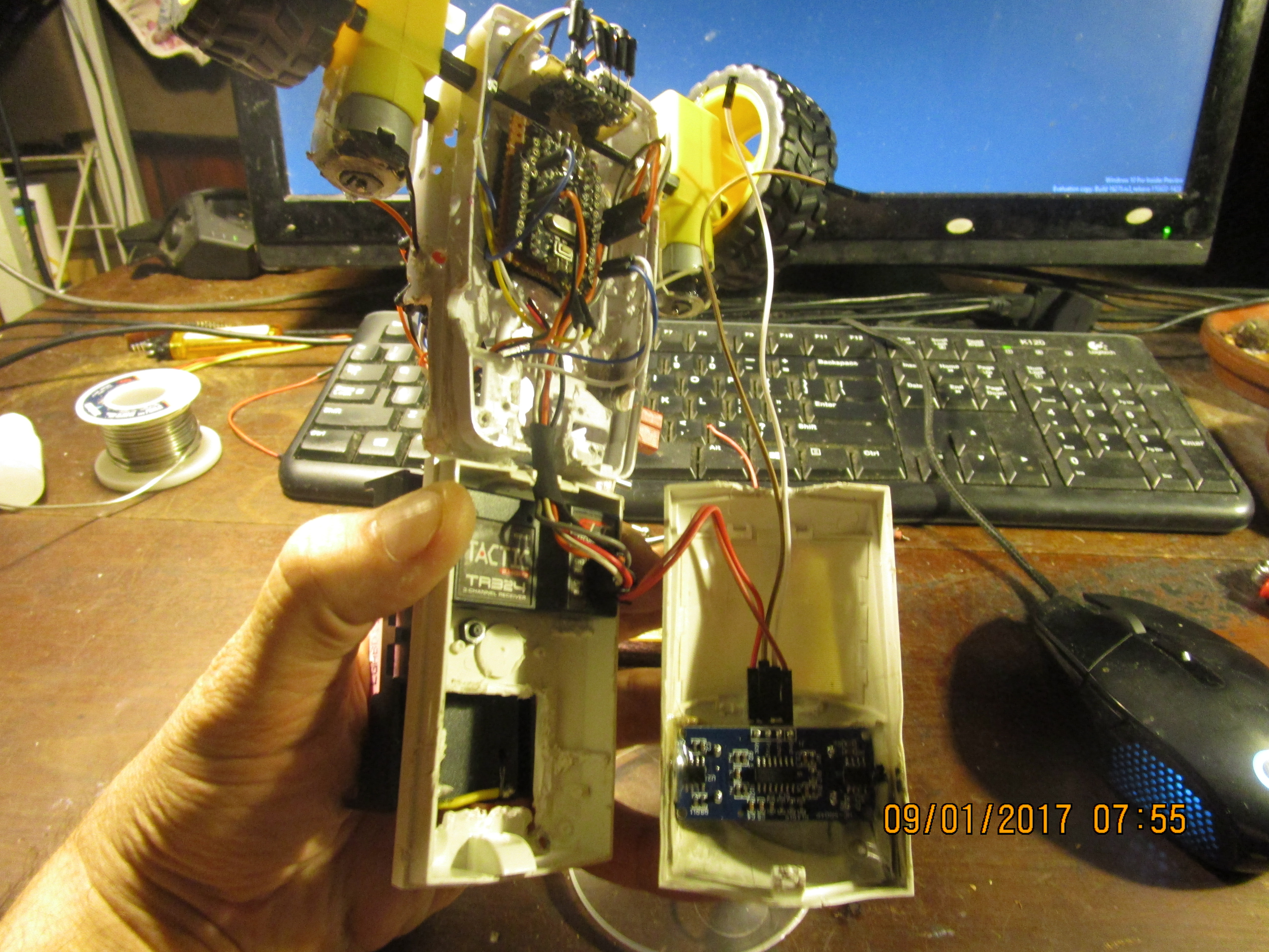
This project uses some abnormal hardware, such as the 6 channel RC receiver module. Although you can use one with fewer channels, this project will remain using 6. Lets get this one out of the way right now, as it is the main focus of this posting for the project.
The PWM signal difference: RC receiver vs the Arduino.
- The PWM signal for the RC receiver is sent out in a microsecond pulse, between 1000-low and 2000-high.
- The PWM signal for the Arduino H-Bridge motor module is a power pulse, between 0-low and 255-high.
- We are using interrupts to gather the RC receiver signals, this is a way to time the duration of the pulse and assign it a value the Arduino can work with.
- The basic calculation between signal types is quick and easy.
Project Perspective
This project is a sophisticated exploration of robotics and control theory. By using an Arduino and an MPU6050 Inertial Measurement Unit (IMU), you can build a two-wheeled robot that stays upright on its own, much like a Segway. This project is a perfect testbed for learning about PID control and real-time sensor fusion.
Technical Implementation: The Art of Balance
The robot's ability to balance depends on a high-speed feedback loop:
- Sensing layer: The MPU6050 measures the robot's tilt angle (pitch) at hundreds of times per second.
- Control layer: The Arduino runs a PID (Proportional-Integral-Derivative) algorithm to calculate the necessary motor response to counteract any tilt.
- Response layer: High-Torque DC Motors accelerate the wheels in the direction of the fall, effectively moving the robot back under its center of mass.
Hardware Infrastructure
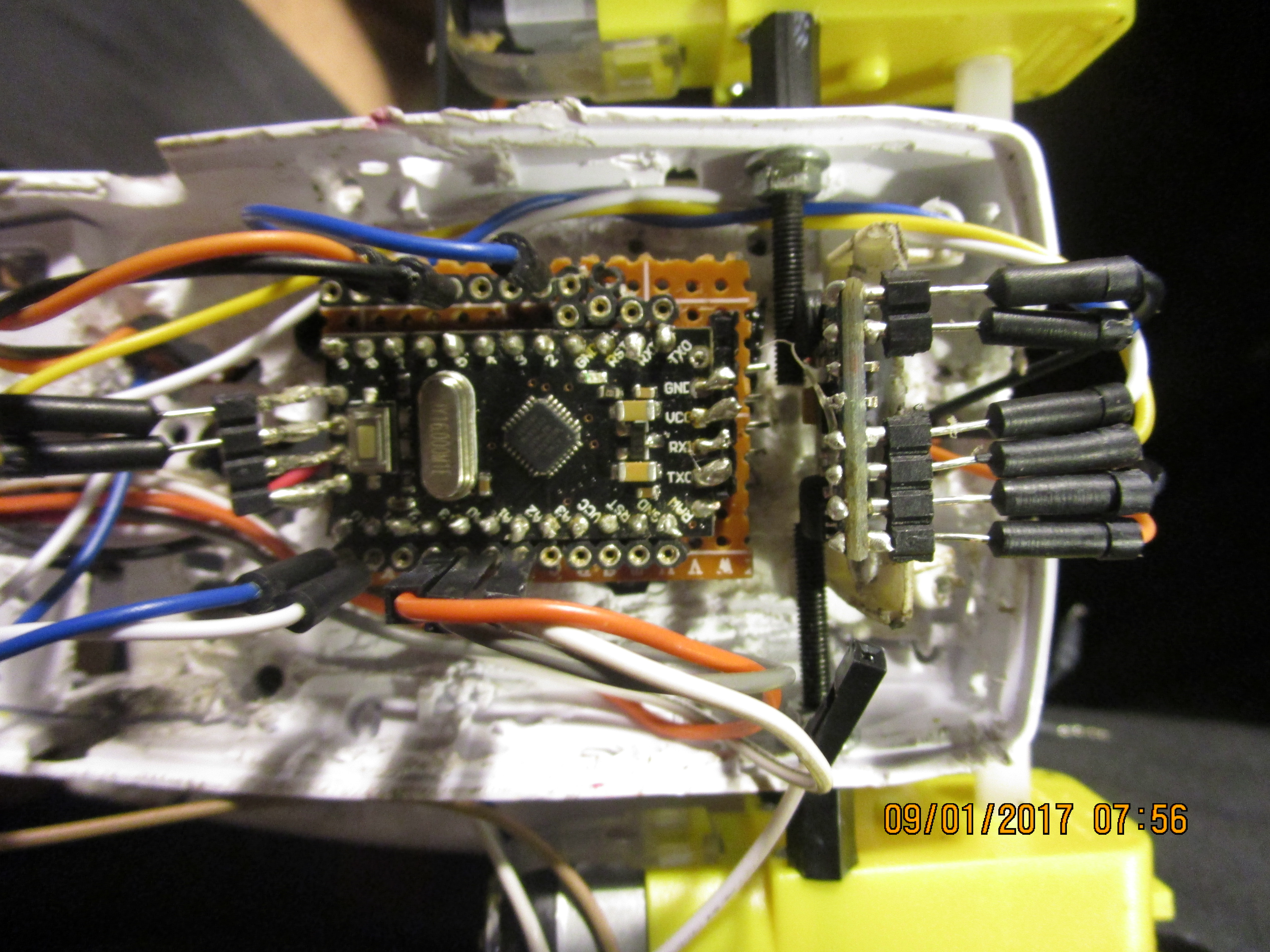
- Arduino Uno: The primary controller managing the PID loop and coordinating motor movements.
- MPU6050 IMU: The "inner ear" of the robot, providing 6-axis motion data for precise angle calculation.
- High-Torque Motors with Encoders: Encoders are crucial for measuring wheel rotation and ensuring the motors are spinning at the exact speeds required by the PID controller.
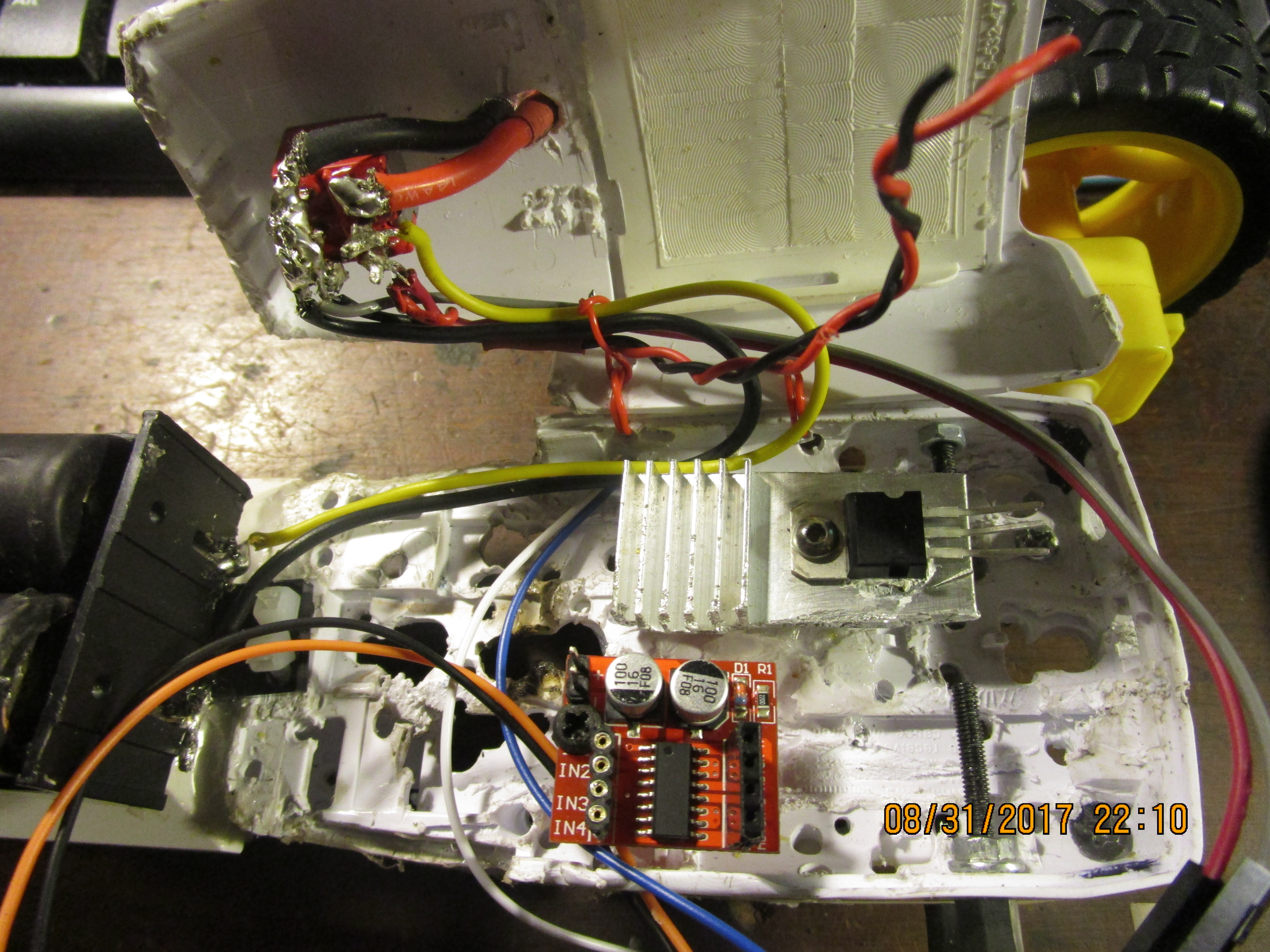
- Motor Driver: Translates the Arduino's digital signals into high-current power for the motors.
- Li-ion/Lipo Battery: Provides the high-discharge current needed for rapid motor movements.
Software Logic & PID Tuning
The Arduino code is the heart of the robot's stability:
- Sensor Fusion: Combine accelerometer and gyroscope data using a Complementary or Kalman filter to get a stable, noise-free tilt angle.
- PID Loop: The
PID.calculate(targetAngle, currentAngle)function produces a PWM output for the motor driver. - Tuning: Finding the right values for Kp (Proportional), Ki (Integral), and Kd (Derivative) is an iterative process that determines how aggressively or smoothly the robot balances.
Sample
Below is a sample of the serial monitor output window.
Cycle #89
Clear distance to front:	0-In	0-Cm
	    Temperature:	21-C	71-F
   System Arming State:	Disarmed
    Transmission State: 	Neutral
	     Turn State:	Going Straight
	     Spin State:	Not Spinning
        Throttle State: 	0%
 Right Stick Horizontal:	Remote CH1	1496-126
   Right Stick Verticle:	Remote CH2	1512-130
  Left Stick Horizontal:	Remote CH4	1444-113
    Left Stick Verticle:	Remote CH3	1000-0
   Arming switch signal:	Remote CH5	1992-252
  Mode Dial(Delay time):	Remote CH6	1992-252
Gyro Motion-Acceleration:	AX-4148		AY-448		AZ17456
   Gyro Motion-Rotation:	GX-1034		GY361		GZ-105
      Gyro Acceleration:	AX-4116		AY-568		AZ17408
          Gyro Rotation:	GX-1023		GY363		GZ-53
Code is long, and may require more than a couple minutes for you to comprehend, skill based of course.
The functions of the RC receiver are as follows:
- CH1 - Left/Right turn
- CH2 - Transmission Forward/Neutral/Reverse
- CH3 - Throttle
- CH4 - Left/Right spin (Only usable if transmission is in neutral)
- CH5 - Arming/Disarming switch
- CH6 - System delay adjustment (increases/decreases the main delay in main loop)
Future Expansion
- Remote Control: Add a Bluetooth or WiFi module (HC-05/ESP8266) to drive the balancing robot from your smartphone.
- Obstacle Avoidance: Integrate an ultrasonic sensor to automatically steer the robot away from walls and furniture.
- Autonomous Navigation: Use GPS or SLAM (Simultaneous Localization and Mapping) for more complex path-finding.
- Fuzzy Logic Integration: Use fuzzy logic to refine the PID controller for even more robust balancing under varying conditions.
This project is a perfect combination of Mechanical Engineering, Electronics, and Control Theory Algorithms.
Video
The code is 440 lines long so far.
#include <EnableInterrupt.h>
#include <NewPing.h>
#include "I2Cdev.h"
#include "MPU6050.h"
#include "Wire.h"
#define SERIAL_PORT_SPEED 57600
#define TRIGGER_PIN  3
#define ECHO_PIN     4
#define MAX_DISTANCE 500
NewPing sonar(TRIGGER_PIN, ECHO_PIN, MAX_DISTANCE);
#define OUTPUT_READABLE_ACCELGYRO
MPU6050 accelgyro;
#define heartbeat_pin 7
int heartbeatDelay=10;
int delayTime=0;
int count = 0;
int delayMultiplier=2;
int16_t ax, ay, az;
int16_t gx, gy, gz;
int16_t ax1, ay1, az1;
int16_t gx1, gy1, gz1;
int x, x1;
int y, y1;
int z, z1;
int temp=0;
int tempC=0;
int tempF=0;
#define RC_NUM_CHANNELS  6
#define RC_CH1  0
#define RC_CH2  1
#define RC_CH3  2
#define RC_CH4  3
#define RC_CH5  4
#define RC_CH6  5
#define RC_CH1_INPUT  A0
#define RC_CH2_INPUT  A1
#define RC_CH3_INPUT  A2
#define RC_CH4_INPUT  A3
#define RC_CH5_INPUT  8
#define RC_CH6_INPUT  9
uint16_t rc_values[RC_NUM_CHANNELS];
uint32_t rc_start[RC_NUM_CHANNELS];
volatile uint16_t rc_shared[RC_NUM_CHANNELS];
bool left_turn = false;
bool right_turn = false;
bool left_spin = false;
bool right_spin = false;
bool not_spinning=true;
bool straight = true;
bool reverse = false;
bool forward = false;
bool brakes = false;
bool neutral = true;
bool armed = false;
int rc_input_Deadzone = 20;
int rc_input_MIN = 1000;
int rc_input_MAX = 2000;
int pwm_MIN = 0;
int pwm_MAX = 255;
int pwm_ch1 = 0;
int pwm_ch2 = 0;
int pwm_ch3 = 0;
int pwm_ch4 = 0;
int pwm_ch5 = 0;
int pwm_ch6 = 0;
int arming_MIN = 20;
int arming_MAX = 230;
int forward_AT = 150;
int reverse_AT = 90;
int left_AT = 150;
int right_AT = 90;
int throttle=0;
int LF_motor_pin = 5;
int LR_motor_pin = 6;
int RF_motor_pin = 10;
int RR_motor_pin = 11;
int L_motor_speed = 0;
int R_motor_speed = 0;
int outMax = 255;
int outMin = 0;
float lastInput = 0;
double ITerm = 0;
double kp = 2;         // Proportional value
double ki = 0;           // Integral value
double kd = 0;           // Derivative value
double Setpoint = 0;     // Initial setpoint is 0
double Compute(double input) {
 double error = Setpoint - input;
 ITerm += (ki * error);
 if (ITerm > outMax) ITerm = outMax;
 else if (ITerm < outMin) ITerm = outMin;
 double dInput = (input - lastInput);
 // Compute PID Output
 double output = kp * error + ITerm + kd * dInput;
 if (output > outMax) output = outMax;
 else if (output < outMin) output = outMin;
 // Remember some variables for next time
 lastInput = input;
 return output;
}
void SetSetpoint(double d) {
 Setpoint = d;
}
double GetSetPoint() {
 return Setpoint;
}
void rc_read_values() {
 noInterrupts();
 memcpy(rc_values, (const void *)rc_shared, sizeof(rc_shared));
 interrupts();
}
void calc_input(uint8_t channel, uint8_t input_pin) {
 if (digitalRead(input_pin) == HIGH) {
   rc_start[channel] = micros();
 } else {
   uint16_t rc_compare = (uint16_t)(micros() - rc_start[channel]);
   rc_shared[channel] = rc_compare;
 }
}
void calc_ch1() {
 calc_input(RC_CH1, RC_CH1_INPUT);
 if (rc_values[RC_CH1] < rc_input_MIN) {
   rc_values[RC_CH1] = rc_input_MIN;
 }
 if (rc_values[RC_CH1] > rc_input_MAX) {
   rc_values[RC_CH1] = rc_input_MAX;
 }
}
void calc_ch2() {
 calc_input(RC_CH2, RC_CH2_INPUT);
 if (rc_values[RC_CH2] < rc_input_MIN) {
   rc_values[RC_CH2] = rc_input_MIN;
 }
 if (rc_values[RC_CH2] > rc_input_MAX) {
   rc_values[RC_CH2] = rc_input_MAX;
 }
}
void calc_ch3() {
 calc_input(RC_CH3, RC_CH3_INPUT);
 if (rc_values[RC_CH3] < rc_input_MIN) {
   rc_values[RC_CH3] = rc_input_MIN;
 }
 if (rc_values[RC_CH3] > rc_input_MAX) {
   rc_values[RC_CH3] = rc_input_MAX;
 }
}
void calc_ch4() {
 calc_input(RC_CH4, RC_CH4_INPUT);
 if (rc_values[RC_CH4] < rc_input_MIN) {
   rc_values[RC_CH4] = rc_input_MIN;
 }
 if (rc_values[RC_CH4] > rc_input_MAX) {
   rc_values[RC_CH4] = rc_input_MAX;
 }
}
void calc_ch5() {
 calc_input(RC_CH5, RC_CH5_INPUT);
 if (rc_values[RC_CH5] < rc_input_MIN) {
   rc_values[RC_CH5] = rc_input_MIN;
 }
 if (rc_values[RC_CH5] > rc_input_MAX) {
   rc_values[RC_CH5] = rc_input_MAX;
 }
}
void calc_ch6() {
 calc_input(RC_CH6, RC_CH6_INPUT);
 if (rc_values[RC_CH6] < rc_input_MIN) {
   rc_values[RC_CH6] = rc_input_MIN;
 }
 if (rc_values[RC_CH6] > rc_input_MAX) {
   rc_values[RC_CH6] = rc_input_MAX;
 }
}
void print_rc_values() {
 Serial.print("  Right Stick Horizontal:\t"); Serial.print("Remote CH1\t"); Serial.print(rc_values[RC_CH1]); Serial.print("-"); Serial.println(pwm_ch1);
 Serial.print("    Right Stick Verticle:\t"); Serial.print("Remote CH2\t"); Serial.print(rc_values[RC_CH2]); Serial.print("-"); Serial.println(pwm_ch2);
 Serial.print("   Left Stick Horizontal:\t"); Serial.print("Remote CH4\t"); Serial.print(rc_values[RC_CH4]); Serial.print("-"); Serial.println(pwm_ch4);
 Serial.print("     Left Stick Verticle:\t"); Serial.print("Remote CH3\t"); Serial.print(rc_values[RC_CH3]); Serial.print("-"); Serial.println(pwm_ch3);
 Serial.print("    Arming switch signal:\t"); Serial.print("Remote CH5\t"); Serial.print(rc_values[RC_CH5]); Serial.print("-"); Serial.println(pwm_ch5);
 Serial.print("   Mode Dial(Delay time):\t"); Serial.print("Remote CH6\t"); Serial.print(rc_values[RC_CH6]); Serial.print("-"); Serial.println(pwm_ch6);
}
void set_rc_pwm() {
 pwm_ch1 = map(rc_values[RC_CH1], rc_input_MIN, rc_input_MAX, pwm_MIN, pwm_MAX);
 if (pwm_ch1 < pwm_MIN) {    pwm_ch1 = pwm_MIN;  }
 if (pwm_ch1 > pwm_MAX) {    pwm_ch1 = pwm_MAX;  }
 pwm_ch2 = map(rc_values[RC_CH2], rc_input_MIN, rc_input_MAX, pwm_MIN, pwm_MAX);
 if (pwm_ch2 < pwm_MIN) {    pwm_ch2 = pwm_MIN;  }
 if (pwm_ch2 > pwm_MAX) {    pwm_ch2 = pwm_MAX;  }
 pwm_ch3 = map(rc_values[RC_CH3], rc_input_MIN, rc_input_MAX, pwm_MIN, pwm_MAX);
 if (pwm_ch3 < pwm_MIN) {    pwm_ch3 = pwm_MIN;  }
 if (pwm_ch3 > pwm_MAX) {    pwm_ch3 = pwm_MAX;  }
 pwm_ch4 = map(rc_values[RC_CH4], rc_input_MIN, rc_input_MAX, pwm_MIN, pwm_MAX);
 if (pwm_ch4 < pwm_MIN) {    pwm_ch4 = pwm_MIN;  }
 if (pwm_ch4 > pwm_MAX) {    pwm_ch4 = pwm_MAX;  }
 pwm_ch5 = map(rc_values[RC_CH5], rc_input_MIN, rc_input_MAX, pwm_MIN, pwm_MAX);
 if (pwm_ch5 < pwm_MIN) {    pwm_ch5 = pwm_MIN;  }
 if (pwm_ch5 > pwm_MAX) {    pwm_ch5 = pwm_MAX;  }
 pwm_ch6 = map(rc_values[RC_CH6], rc_input_MIN, rc_input_MAX, pwm_MIN, pwm_MAX);
 if (pwm_ch6 < pwm_MIN) {    pwm_ch6 = pwm_MIN;  }
 if (pwm_ch6 > pwm_MAX) {    pwm_ch6 = pwm_MAX;  }
}
void Ping() {
 Serial.print("Clear distance to front:\t");
 Serial.print(sonar.ping_in());
 Serial.print("-In\t");
 Serial.print(sonar.ping_cm());
 Serial.println("-Cm");
}
void delay_time(){
 delayTime=pwm_ch6*delayMultiplier;
   delay(delayTime);
}
void arming_state() {
 Serial.print("    System Arming State:\t");
 if (pwm_ch5 <= arming_MIN) {
   armed = true;
   Serial.println("Armed");
 } else if (pwm_ch5 >= arming_MAX) {
   armed = false;
   Serial.println("Disarmed");
 }
}
void spin_state(){
   Serial.print("\t     Spin State:\t");
     if (pwm_ch4 > left_AT) {
   left_spin = true;
   right_spin = false;
   not_spinning = false;
   Serial.println("Spinning Left");
 }
 if (pwm_ch4 &