Introduction:
The reception of an audio signal and converting it into visual or mechanical reaction is very interesting. In this project we shall use an Arduino Mega to be connected to a spectrum analyzer MSGEQ7 that takes the input audio signal and perform band pass filtering on it to divide it into 7 main frequency bands. The Arduino will then analyze the analogue signal of each frequency band and creates an action.
Objectives:
This project will discuss 3 modes of operation:
- LEDs are connected to PWM digital pins to react to the frequency bands
- LEDs are connected to digital pins to react to the frequency bands
- Pumps are connected to the Arduino Mega through Motor drivers and react to the frequency bands
Theory:
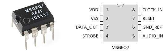
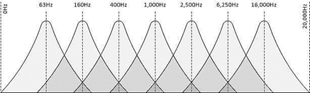
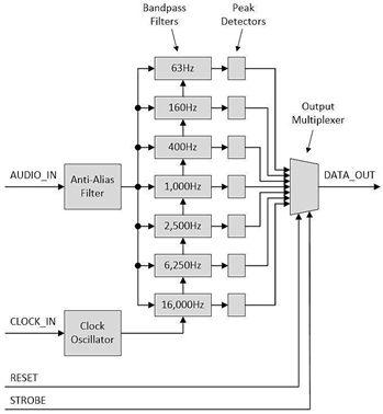
If we talk about the MSGEQ7 Spectrum Analyzer IC we can say that it has internal 7 band pass filters that divides the input audio signal into 7 main bands: 63 Hz, 160 Hz, 400 Hz, 1 kHz, 2.5 kHz, 6.25 kHz and 16 kHz.
The output of each filter is chosen to be the output of the IC by using a multiplexer. That multiplexer has selectors lines controlled by an internal binary counter. So we can say that the counter should count from 0 to 6 (000 to 110) to allow one band to pass at a time. That makes it clear that the code of the Arduino should be able to reset the counter once it reaches the count 7.
If we have a look on the circuit diagram of the MSGEQ7 we can see that we use RC frequency tuner to control the internal clock of the oscillator. then we use filtering RC elements at the input audio signal port.
The Hardware Advantage: MSGEQ7
Calculating a Fast Fourier Transform (FFT) on an Arduino Uno is slow and eats all the RAM. The MSGEQ7 chip solves this elegantly.
- It is an analog piece of hardware. You plug a headphone jack directly into it.
- In real-time, it splits the audio signal into exactly 7 frequency bands (63Hz, 160Hz, 400Hz, 1kHz, 2.5kHz, 6.25kHz, 16kHz).
- The Strobe Pin: The Arduino pulses the MSGEQ7's Strobe pin. With every pulse, the chip outputs a DC voltage (0-5V) on its
OUTpin corresponding to the volume of that specific frequency band. - The Arduino just uses rapid
analogRead()in aforloop, saving all 7 band volumes instantly!
Procedures:
According to the source page (https://www.baldengineer.com/msgeq7-simple-spectrum-analyzer.html) we can see that the source code deals with the outputs as PWM signals that is repetitive. we can change some of the code lines to suite our goals.
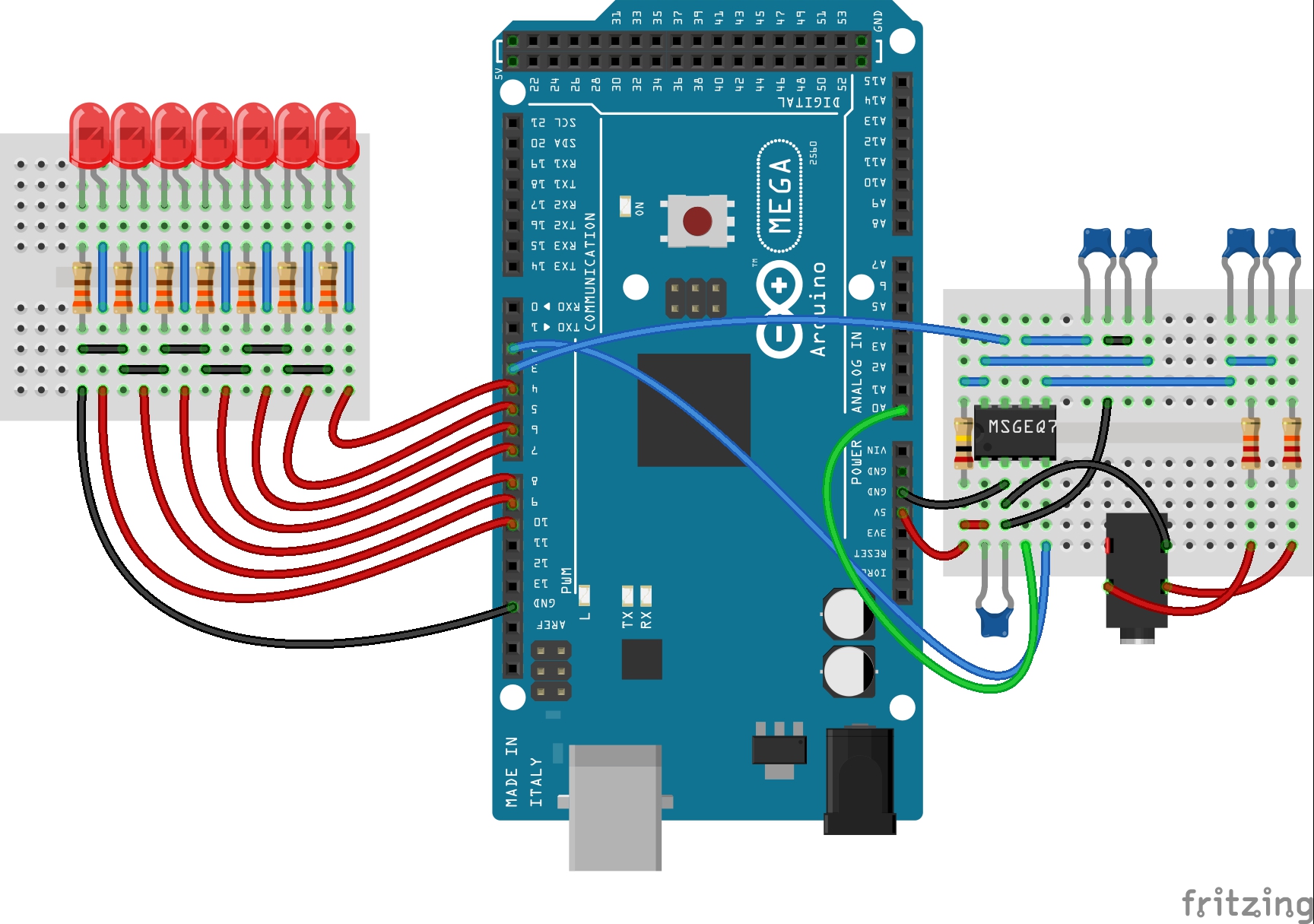
First we connect the MSGEQ7 IC on a mini breadboard as per the following schematic:
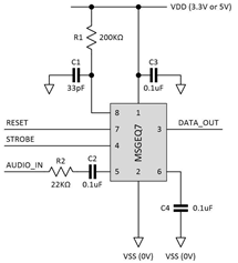
We can notice that if we have a stereo jack, we can double the input resistor and capacitor to the second channel.
We power the MSGEQ7 from the Arduino VCC (5 volts) and GND. We shall connect the MSGEQ7 to the Arduino board. I prefer to use the Arduino Mega as it has PWM pins suitable for the project. The output of the MSGEQ7 IC is connected to analogue pin A0, the STROBE is connected to pin 2 of the Arduino Mega and the RESET is connected to pin 3.
Actuating the Water
With the math solved by the MSGEQ7, the physical build begins. The core logic is simple:
if (band63Hz > 800): The low bass hits! The Arduino triggers a 5V relay or MOSFET.- The relay or MOSFET activates a 12V Submersible Water Pump.
- A jet of water shoots straight up from your custom PVC pipe fountain!
- The remaining 6 pumps are mapped to the other 6 frequency bands.
Modes of operation:
LEDs as PWM digital outputs: according to the source code, we can connect the output LEDs to pins 4 thru 10
constintLED_pins[7] ={4,5,6,7,8,9,10};
Then we can notice the LEDs dances upon the strength of each frequency band.
The suggested code shall be as follows:
#define msg7RESET 3
#define msg7Strobe 2
#define msg7DCout 0
const int LEDpins[7] = {4,5,6,7,8,9,10};
void setup()
{
for (int x=0; x<7; x++)
{
pinMode(LEDpins[x], OUTPUT);
}
pinMode(msg7RESET, OUTPUT);
pinMode(msg7Strobe, OUTPUT);
}
void
{
digitalWrite(msg7RESET, HIGH);
delay(5);
digitalWrite(msg7RESET, LOW);
for (int x = 0 ; x < 7 ; x++)
{
digitalWrite(msg7Strobe, LOW);
delayMicroseconds(35);
int spectrumRead = analogRead(msg7DCout);
int PWMvalue = map(spectrumRead, 0, 1024, 0, 255);
if (PWMvalue < 50)
PWMvalue = PWMvalue / 2;
analogWrite(LEDpins[x], PWMvalue);
digitalWrite(msg7Strobe, HIGH);
}
}
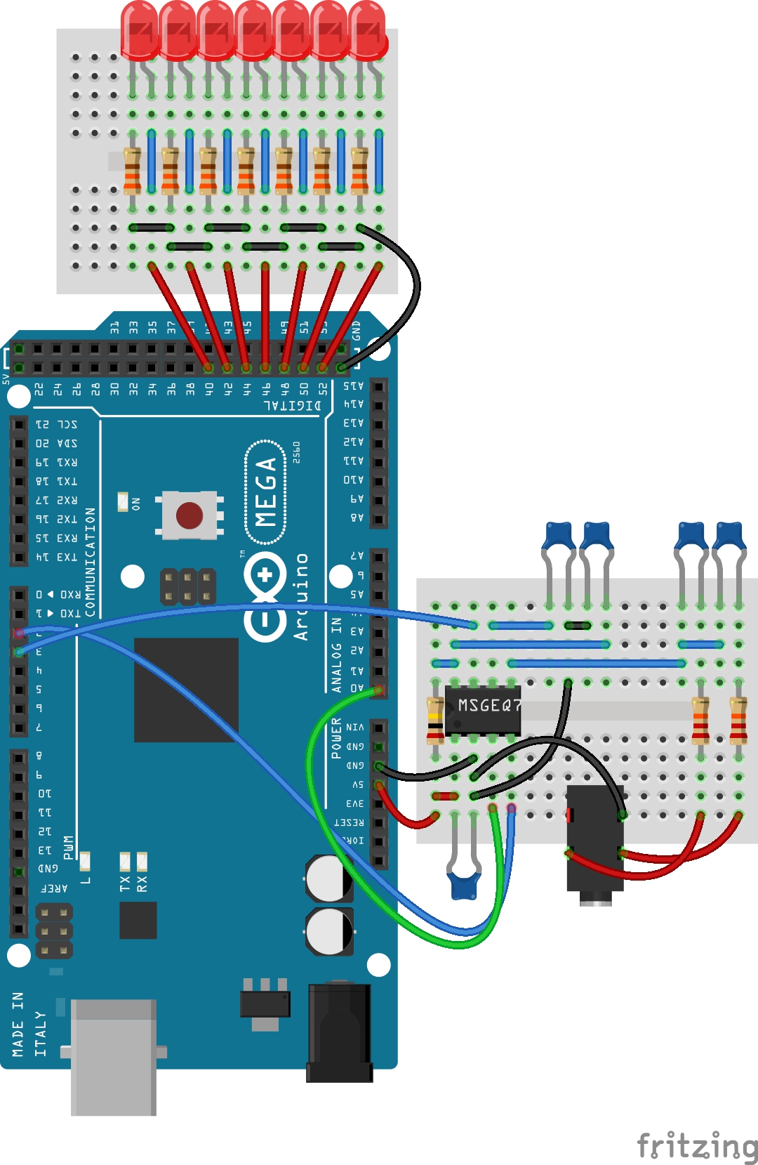
LEDs as digital outputs:
We can connect the output LEDs to any digital pins.
constintLED_pins[7] ={40,42,44,46,48,50,52};
Then we can notice the LEDs flashes upon the strength of each frequency band.
The following video shows the results of the conenctions:
The suggested code shall be as follows:
#define msg7RESET 3
#define msg7Strobe 2
#define msg7DCout 0
const int LEDpins[7] = {40,42,44,46,48,50,52};
void setup()
{
for (int x=0; x<7; x++)
{
pinMode(LEDpins[x], OUTPUT);
}
pinMode(msg7RESET, OUTPUT);
pinMode(msg7Strobe, OUTPUT);
}
void
{
digitalWrite(msg7RESET, HIGH);
delay(5);
digitalWrite(msg7RESET, LOW);
for (int x = 0 ; x < 7 ; x++)
{
digitalWrite(msg7Strobe, LOW);
delayMicroseconds(35);
int spectrumRead = analogRead(msg7DCout);
int PWMvalue = map(spectrumRead, 0, 1024, 0, 255);
if (PWMvalue < 50)
PWMvalue = PWMvalue / 2;
analogWrite(LEDpins[x], PWMvalue);
digitalWrite(msg7Strobe, HIGH);
}
}
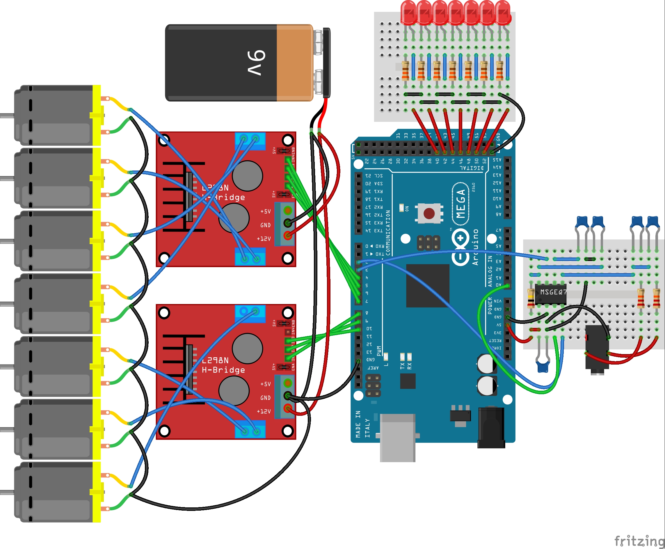
Pumps as Digital outputs:
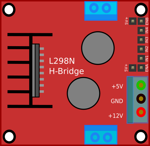
In this last mode we shall connect L298N motor driver module to the outputs of the Arduino. This enables us to control the operation of the pump based on the output of the MSGEQ7 spectrum analyzer.
As known, the motor drivers enable us to control the operation of the connected motors or pumps based on the generated signal from the Arduino without sinking any current from the Arduino, instead they power the motors directly from the connected power source. Then we can connect the motor drivers to the Arduino as shown in the following image:
If we run the code as raw source, the pumps may not operate properly. That is because the PWM signal is low and will not be suitable for the motor driver to run the motors or pumps and deliver a suitable current. That is why I recommend to increase the PWM value by multiplying the analogue readings from A0 with factor larger than 1.3. This helps the mapping to be suitable for the motor driver. I recommend 1.4 to 1.6. Also we can remap the PWM to be 50 to 255 in order to be sure that the PWM value will be suitable.
The suggested code shall be as follows:
#define msg7RESET 3
#define msg7Strobe 2
#define msg7DCout 0
const int LEDpins[7] = {40,42,44,46,48,50,52};
const int Pumppins[7] = {4,5,6,7,8,9,10};
void setup()
{
for (int x=0; x<7; x++)
{
pinMode(LEDpins[x], OUTPUT);
}
pinMode(msg7RESET, OUTPUT);
pinMode(msg7Strobe, OUTPUT);
}
void
{
digitalWrite(msg7RESET, HIGH);
delay(5);
digitalWrite(msg7RESET, LOW);
for (int x = 0 ; x < 7 ; x++)
{
digitalWrite(msg7Strobe, LOW);
delayMicroseconds(35);
int spectrumRead = analogRead(msg7DCout*1.45);
if (spectrumRead >= 1023)
{
spectrumRead = 1023;
}
int PWMvalue = map(spectrumRead, 0, 1024, 50, 255);
if (PWMvalue < 75)
PWMvalue = PWMvalue / 2;
analogWrite(Pumppins[x], PWMvalue);
analogWrite(LEDpins[x], PWMvalue);
digitalWrite(msg7Strobe, HIGH);
}
}
We can connect the LEDs together with the outputs for the motor drivers, but the LEDs will not flash in a good visible way like before as the PWM values have been increased. So I suggest to keep them connected to the digital pins 40 thru 52.
Necessary Parts
To build a complete audio-reactive fountain system, you will need the following key components:
- Arduino Uno/Nano/Mega: The logic controller.
- MSGEQ7 IC Chip + necessary capacitors/resistors.
- 12V Mini Submersible Water Pumps (x7).
- MOSFETs or Relay Boards or L298N Motor Drivers: To handle the pump voltages safely.
- Plastic Tub, PVC pipes, and tubing for constructing the fountain.