This is my second Arduino Project. It is a powerful light that turns on or off depending on the brightness of its surroundings. It also has a manual mode, allowing you to manually toggle the light.
If you build an enclosure for it and calibrate the photocell, this can be used as an outdoor light, which turns off during the day, when it is unnecessary, and turns on at night. For power, this exact circuit only requires one AC wall socket.
Technical Implementation: Sensing and Actuation
The project involves two main functional blocks:
- Sensing layer: The Arduino uses an LDR (Photoresistor) to constantly measure the ambient light level. This 0-5V signal is converted into a 10-bit digital value (0-1023) by the Arduino's ADC.
- Actuation layer: A 220V/5V Relay Module acts as an electronic switch to turn on or off a high-voltage AC light bulb (LED or similar) based on the light readings.
Hardware Infrastructure
- Arduino Uno: The primary controller managing the light sensor and coordinating the relay's ON/OFF activities.
- LDR (Photoresistor): Providing contactless and reliable light monitoring by changing its resistance based on the ambient light level.
- 220V/5V Relay Module: Effectively isolates and controls the high-voltage light bulb with a low-voltage signal.
- Resistor (10k ohm): Used as a voltage divider for the LDR to provide a stable analog signal to the Arduino.
- Micro-USB Cable: Use to program the Arduino directly from your computer for power and data.
Interaction Logic & Hysteresis
The Arduino code is designed to be energy-efficient and reliable:
- Initialize ADC: SETUP the Arduino to read the analog signal from the LDR sensor.
- Threshold Monitoring: The Arduino constantly compares the current light level to a pre-defined threshold (e.g., <300 for dark).
- Execution: If the light level is below the threshold, the Arduino sends a HIGH signal to the relay, turning on the light.
- Hysteresis Logic: Use a small delay and several threshold values to prevent the light from flickering or turning on prematurely during sunset.
I did not complete the process to utilize this practically since school is starting soon for me, and I already had a more robust commercial product with the same functionality lying around.
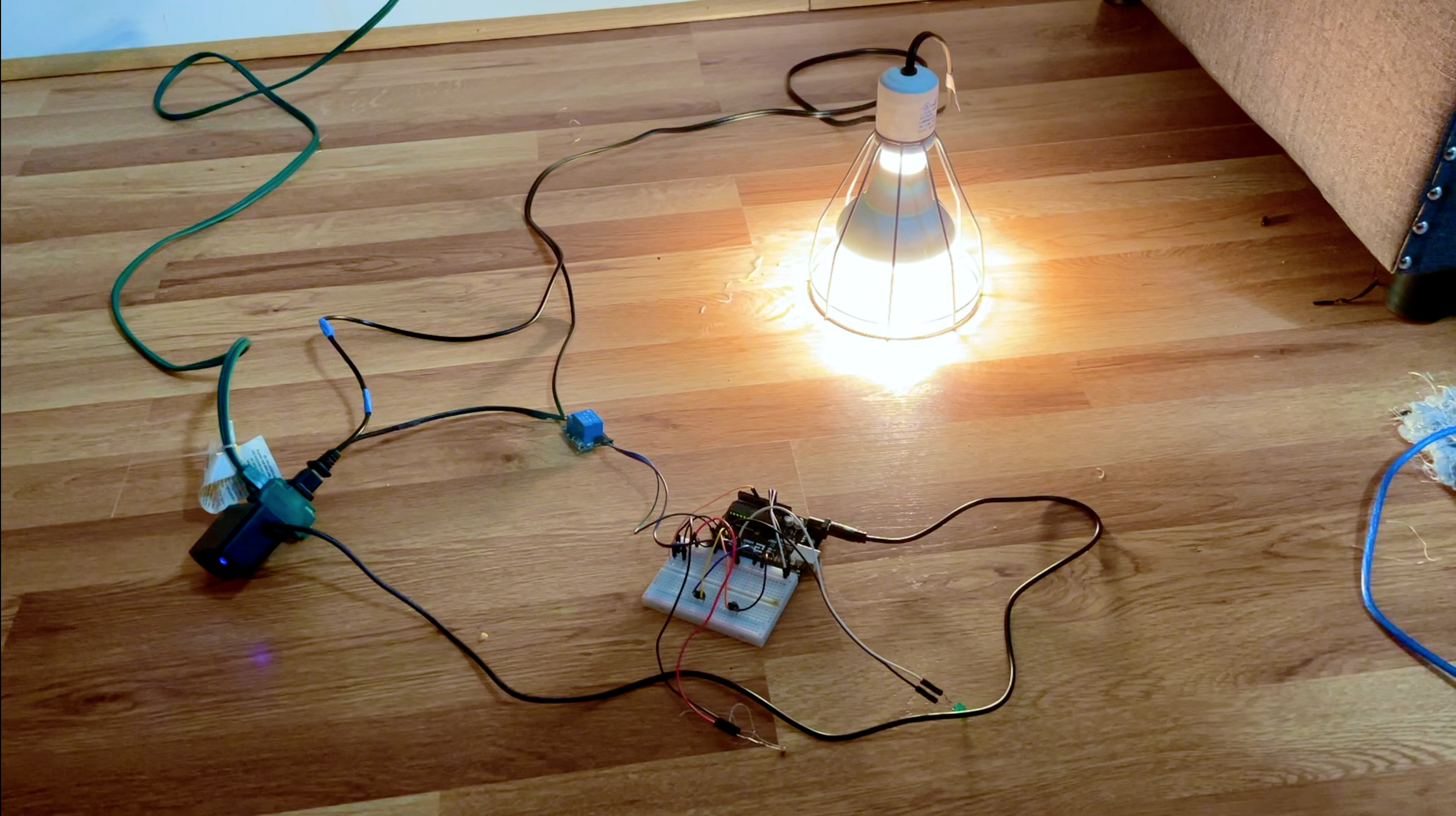
Assuming you are using a generic AC-powered light, like I did, you need to cut one side of its wire (as can be seen in the picture) and remove some insulation so you can plug it into the relay. If you are planning on using this practically, you will likely use a different lighting configuration (e.g. a more power-consuming light, mutiple lights, etc.). For this, you may need to use multiple AC wall sockets. For each extra wall socket, you will need to use another relay. Simply copy the code for one relay and paste it right next to it.
Future Expansion
- Cloud Status Dashboard: Add a WiFi module (ESP8266/ESP32) to log each time the light is activated into a cloud dashboard for energy usage tracking and monitoring.
- PIR Motion Sensor Sync: Integrate a PIR motion sensor to only turn on the light during the night if motion is detected, further improving energy efficiency.
- OLED Identity Dashboard: Add a small OLED display to show the current light level and the number of times the light has been activated.
- Solar Energy Integration: Add a solar panel and battery to make the outdoor light completely self-sufficient and off-grid.
This project is an essential "Hello, World!" for understanding Sensors, Automated Control, and Environment Monitoring.