Half-Duplex Connectivity Forensics
The nRF24L01 RF transceiver module promises intense transmission ranges coupled directly with nominal power footprints. However, these identical metrics frequently trigger significant synchronization failures within custom integrations across hobbyist and professional planes. The core constraint rests in the half-duplex operational matrix. The operational modes dictate strict toggling between Rx (Receiver) and Tx (Transmitter) execution states, requiring precise SPI packet handshakes indicating successful ACKs (acknowledgment boundaries) before buffer flushing.
Often, developers assume dual-node full-function coupling without isolating absolute baseline transceiver functionality. This architecture demands isolating the logic vectors into three separate, identifiable tests focusing on hardware limits and noise ceilings.

Step 1: Ether Node Scanning
Prior to attempting an active connection handshake between disparate nodes, the immediate priority is verifying the functional state of the silicon layout via an Ether Scanner topology (found localized natively within the RF24 library -> Scanner).
By extending isolated channel scanning duration from standard 128 µs limits to 512 µs, noise floors are far more successfully detected in dense environments. Identifying the least saturated local 2.4 GHz spectrum channels (for instance, pushing operational limits above Channel 60 or Hex 0x3C) dramatically enhances ACK handshake continuity limits. A saturated analog space immediately introduces dropped packets regardless of flawless C++ SPI definitions.
Step 2: Unilateral Transmission Polling
Assemble the secondary node strictly executing single-state logic (unidirectional Transmitter vector). Force the payload output toward a static, confirmed clean channel (e.g. 112 / 6f). Simultaneously, observe the primary node (acting strictly as an ether scanner) attempting to locate persistent hex anomalies strictly mapped to your defined output channel array without expecting formal algorithmic ACKs.
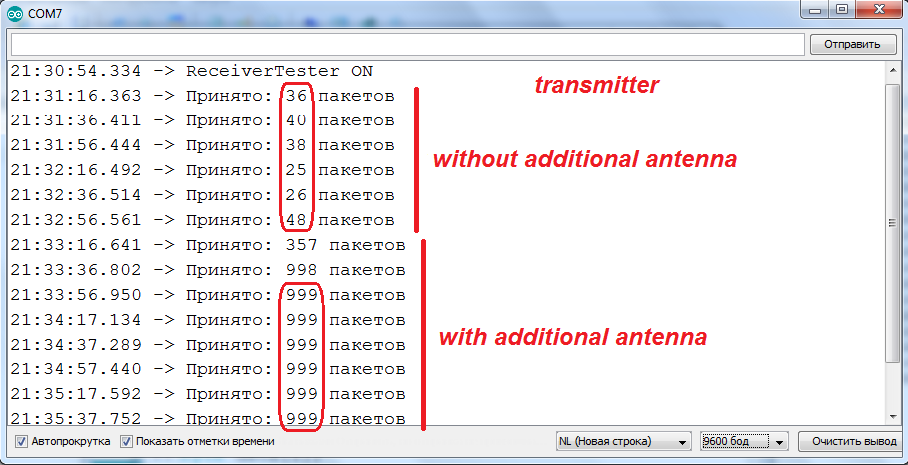
Step 3: Hardware Attenuation and Signal Filtering
This is universally where logical execution fails to compensate for physical constraints. You may configure the perfect C++ loop to catch 999 packets from the 1000 array, but if receiving limits stall at roughly 5% capacity due to invisible physical elements, code abstraction yields zero improvement.
- Antenna Redundancy: Extending internal embedded PCB antennas with a precisely calculated 50 ohm coaxial output array directly mapped parallel to pin
ANT2radically improves geometric RF mapping vectors. - Analog Shunt Topologies: By far the most critical failure point rests in noisy 3.3v step-down rails generated via raw Arduino regulators. Implement heavy parallel capacitance across
VCCandGNDheaders mapping local to the nRF24L01 logic nodes. Coupling a high-pass4.7µF Ceramic Capacitorsimultaneously beside a10µF Electrolytic Capacitoracts as an absolute noise trap. This hardware limit scrubs high-frequency SPI noise from back-feeding over power rails while smoothing massive in-rush current pulses demanded during sudden TX burst states that regularly crash Atmel architectures.