The idea
The idea here is to implement DFT on AVR 8 bit mcu platform with simplest algorithm and achieve real time display of Fourier transform of audio signal.
Before we get started with this project here are few prerequisites you need to know:
- DFT - mathematical representation and significance
- AVR micro-controller: fundamentals and C programming
- Audio electronics
Well if you are aware about the above mentioned topics, lets get started.
As we know 'sound' is caused due to physical disturbance in a medium, these disturbances are created using a speaker which converts sinusoidal electrical signal to displacement. Hence all the sound waves are made from sinusoidal signals. Also any wave can be represented as the weighted sum of sinusoids with angular frequency multiples of base frequency, the below represents mathematical form of any waveform.Here the weights are the amplitudes of the corresponding frequency. The DFT algorithm finds these weights for their corresponding frequency when unknown signal is given.
The DFT algorithm
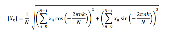
Now the DFT can be computed by the following equation:
The above equation can be directly written in C, before we get into source code lets begin with circuit schematic:
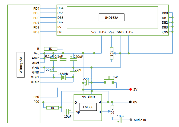
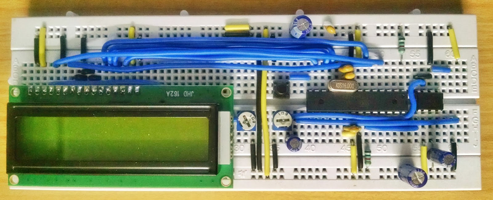
Building the circuit
To build the circuit I have used ATmega328P mcu and JHD162A LCD. The LCD is interfaced with PORT-D of mcu and the LCD is configured in 4 bit data bus mode. LM386 is a dedicated audio amplifier, its purpose here is to amplify the audio signal which has max. amplitude of 0.7V (usually). For proper results we need to tune or set the 10K trimmer pot.. Also the arrangement of capacitor needs to be done so that noise produced is minimum.
Technical Implementation: Sine-Cosine Mapping and Histogram Visualization
The project reveals the hidden layers of simple sensing-to-view interaction:
- Identification layer: The ATMega328p ADC acts as a high-resolution chronological eye, measuring every point of the audio waves via its internal SAR-conversion.
- Conversion layer: The system uses high-speed digital pins to receive high-speed bit-states to coordinate mission-critical sensing tasks.
- Spectrum Interface layer: A 16x2 Custom-Character LCD provides a high-definition visual data dashboard for each frequency status check (e.g., 16 Bins).
- Audio Interface layer: An LM386 Amplifier provides a manual gain-override for audio status checks during initial calibration.
- Processing Logic: The C code follows a "lookup-table" (or DFT-dispatch) strategy: it interprets the sampled audio values and matches frequency bins to provide safe and rhythmic visual spectrum analysis without costly
math.hfunctions.
After uploading the code, on startup the controller sets i/o port, then configures ADC, then loads LCD drivers and then runs a bootup animation...
The DFT code segment starts from 7th line from 'int main()'.
Here I have implemented 32 point DFT so that it can classify the input audio signal to 16 frequencies. For 32 point DFT the mcu needs to compute 512 values of sine and cosine. If the functions of math.h library were used, the computation would require more time so I have made a lookup table in the flash of the mcu because of which the computation has become faster and real time display is achieved.
When the program counter enters the application section (infinite loop) first the input is sampled and is passed over to DFT, the output is displayed in the form of bar-graph (histogram) on LCD these are also called as 'bins'.
Here we are using character LCD, hence we need to define the bars manually by writing the relevant code. This model of LCD allows you to create 8 custom character each of 8 bytes. In the source code I have written a function for creating the custom characters.
Audio Sampling Section
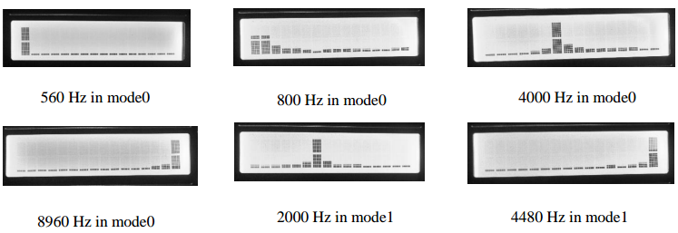
Now lets get into the audio sampling section, when the mcu starts by default it enters into the mode0 which has the sampling frequency of 17.920Ksps, so we get the range of 560 - 8960 Hz according to Nyquist's criterion. The sampling rate is decided with the prescaler value of ADC which is set in ADCSRA register of mcu. Now the button 'SW' is used to set the range i.e. by default 560 - 8960 Hz (mode0) and when pressed it switches to 280 - 4480 Hz (mode1, sampling rate = 8960 Hz) and when pressed again it rolls back to default state. Here the button is switching the value of ADCSRA register. (for more information refer datasheet of mcu)
The output of DFT is in the range of 0 - 32 (approx.)(adjust the trimmer pot accordingly or add a code segment to divide the output with relevant value so the output is scaled) so I have scaled by dividing it by 2 and displayed the output on LCD (refer code).
IMPORTANT: To ensure accurate spectrum analysis, always perform an ADC Offset Calibration (typically centered at 511 bits) in the code; always ensure you have an appropriate Sampling Rate (e.g., 17.92 Ksps) for every audio range you intend to analyse!
Picture of DFT with various inputs and modes:
Now comes the question 'How accurate this device could be?' Well as I have used lookup table approach, to save space in flash I have stored integral values of the sine and cosine by scaling them up by 1000 times and the final result is scaled down by 1000 times so this is not the most accurate device but for accuracy we need to do a proper trade-off between accuracy and speed. As I have opted for real time display I have compromise a bit on accuracy. However this has pretty good accuracy and speed compared to the device which uses functions from math.h library.
Demo
Here is the video of DFT Audio Analyser demonstrating the song 'flute' by Tony Igy
Future Expansion
- OLED Identity Dashboard Integration: Add a small OLED display to show "Peak Frequency" or other metrics.
- Multi-sensor Sync Synchronization: Connect a specialized "Bluetooth Module" to perform higher-precision "Wireless Spectrogram" analysis wirelessly.
- Cloud Interface Registration Support: Add a specialized web-dashboard on a smartphone over WiFi/BT to precisely track and log total audio history logs.
- Advanced Profile Customization Support: Integrate specialized algorithms to allow triggers to be changed automatically based on user input or signal characteristics.
DFT Audio Analyser is a perfect project for any science enthusiast looking for a more interactive and engaging signal tool!
For more projects on Arduino and AVR visit project website