This is my first clock I made in 2004. I made the clock with digital ic's.
I used 4 bit shift registers, so I had to use 33 of them. And to debounce 4 switches I used NAND gates to do the job. Also to make 1 Hz clock, I used several divider ic's to slow down the 1 MHz crystal. My father in law engraved the front.
But the clock went to the attic.
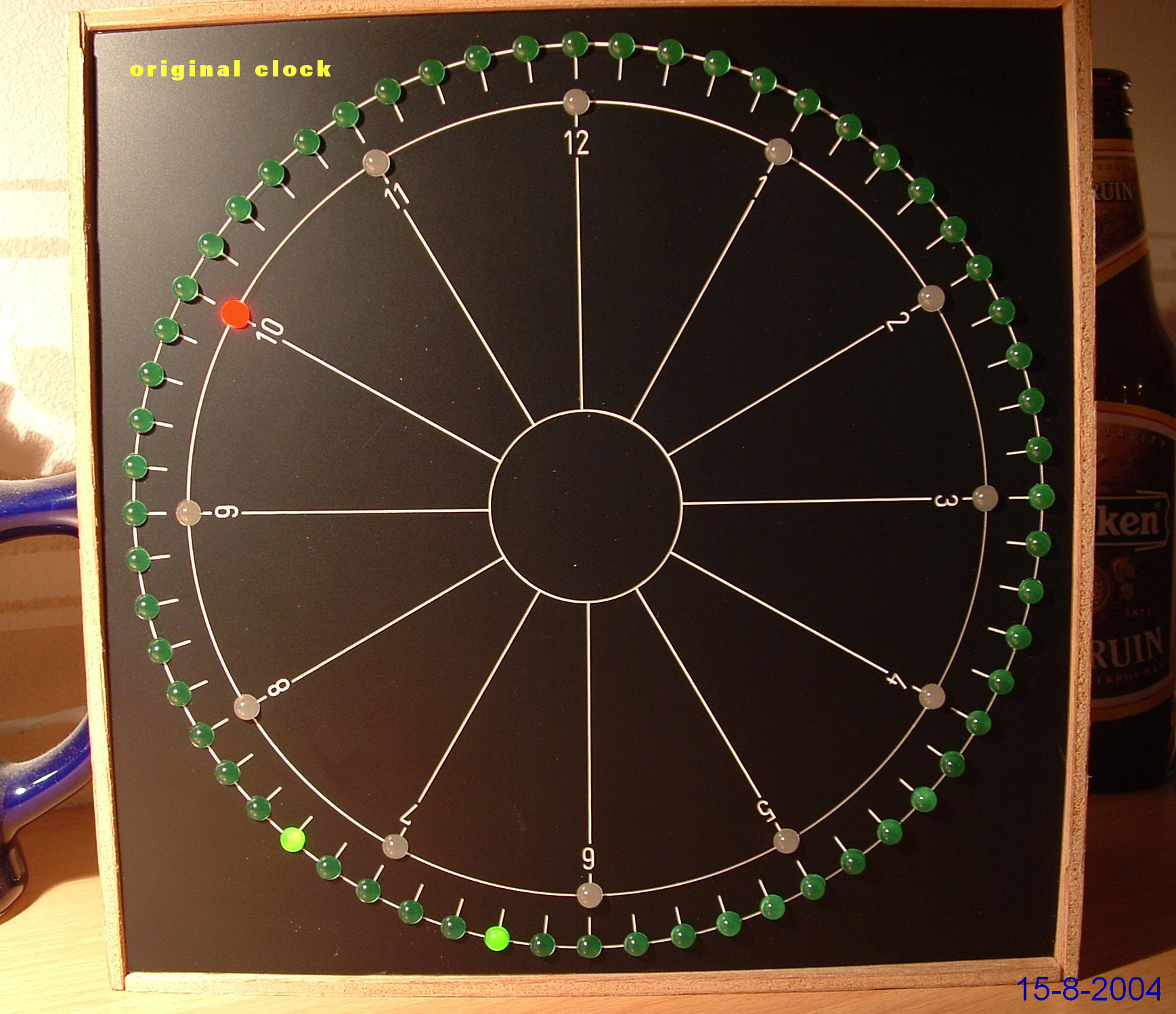
Now I am retired and I rebuild it with arduino. The original clock is shown in the photo below.
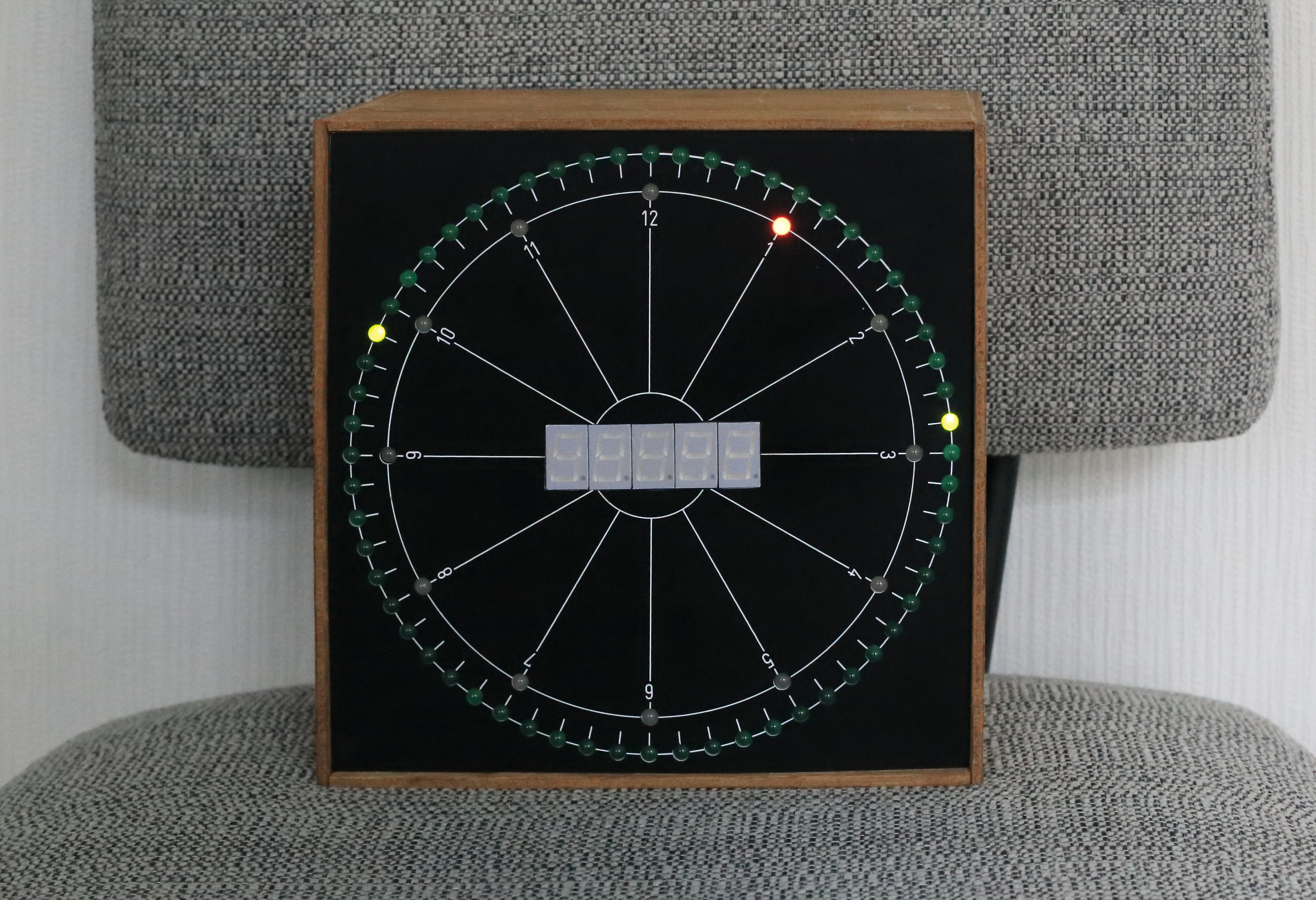
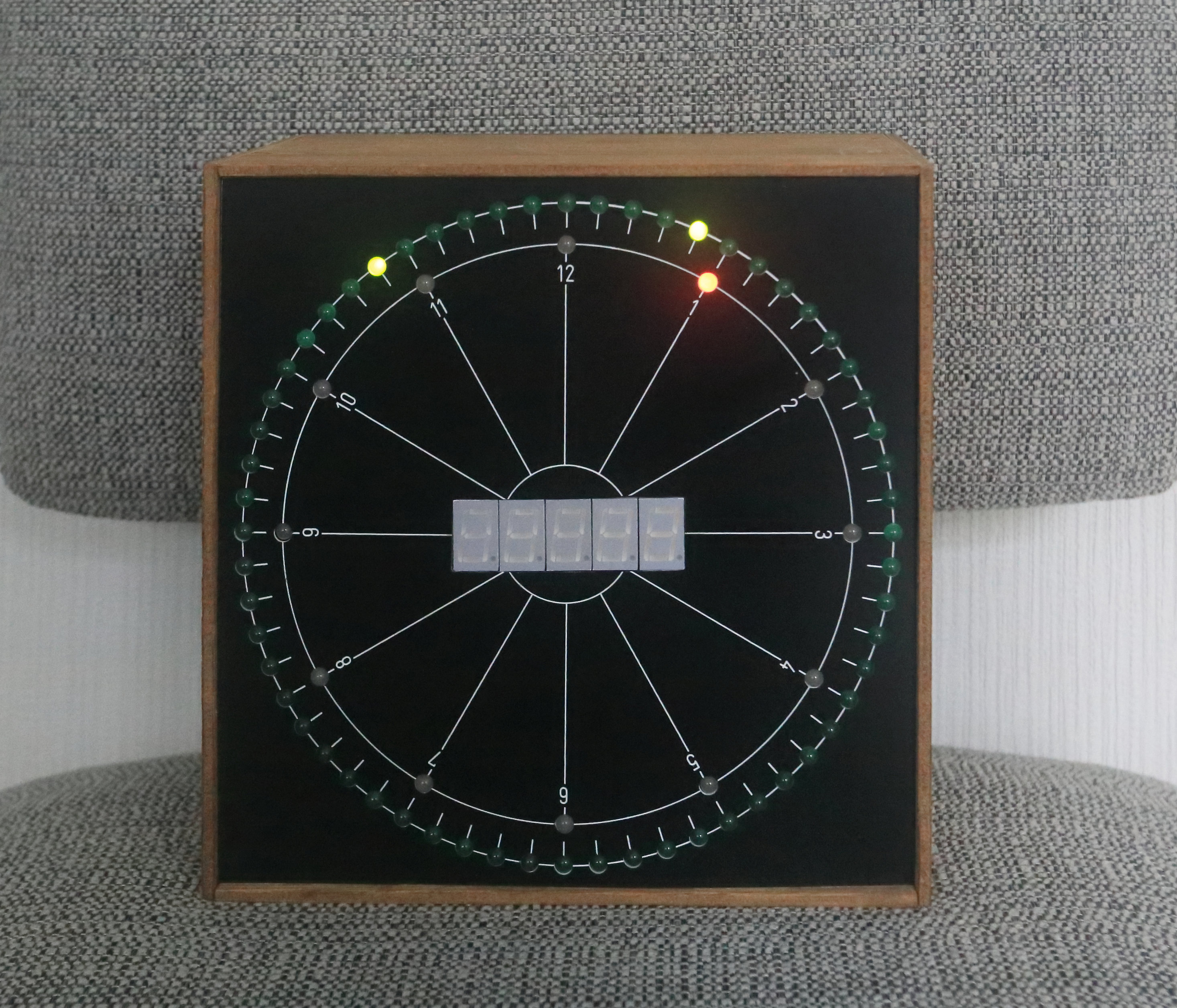
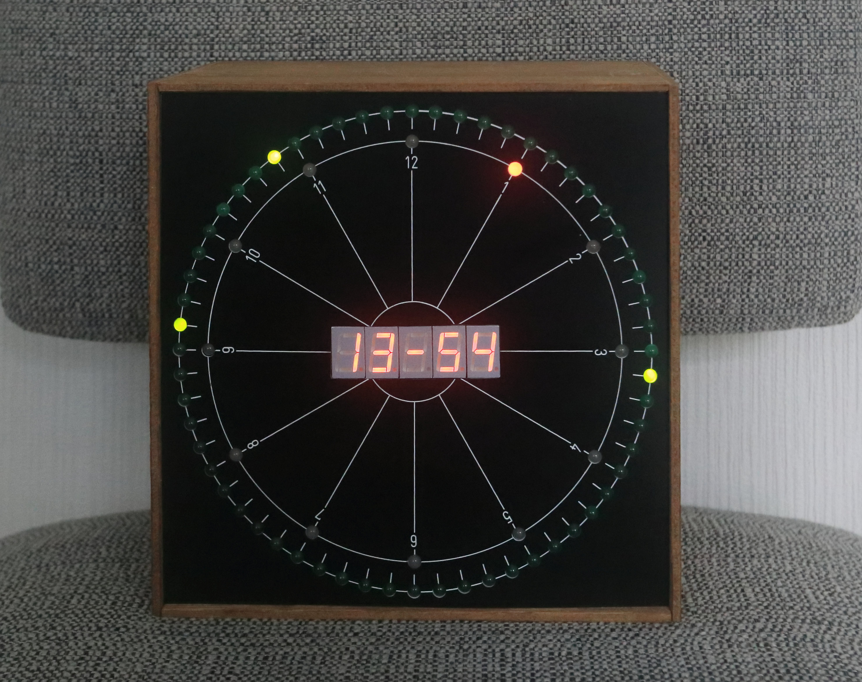
I rebuild the clock and used all the 60 + 12 connections of the leds, so now I need 9 shifregisters (8 bit). Somehow I got a MM5451 35 bit shiftregister mounted on a printboard with 5 displays (7-segment led). I made a hole in the front and placed the displays in it. See photos below.

I made my own routines to read and set the RTC, so there is no need to load a RTC library. I am using the RTC 1 Hz SQW puls via interrupt pin 2 on the arduino. In the main loop the program is checking the state of the 4 switches. With 4 switches there are 16 functions.
Technical Implementation: I2C Time-keeping and Nested Animations
The project reveals the hidden layers of simple time-to-light interaction:
- Identification layer: The DS3231 RTC Module acts as a high-resolution temporal eye, measuring every exact second via its internal temperature-compensated crystal.
- Conversion layer: The system uses high-speed digital pins to receive high-speed PWM pulses to coordinate mission-critical lighting tasks.
- Visual Interface layer: The 60+12 LED rings provide high-resolution visual feedback for the "Hour/Minute/Second" status (e.g., Outer ring = Seconds, Inner ring = Hours).
- Processing Logic layer: The Arduino code follows a "pixel-mapping" (or nested-timing) strategy: it interprets the RTC values and matches the LED indices to provide safe and rhythmic clock patterns.
- Communication Dialogue Loop: Time values are sent rhythmically to the Serial Monitor during initial calibration to coordinate status.
Hardware-Timepiece Infrastructure
- Arduino Nano: The "brain" of the project, managing the multi-directional I2C sampling and coordinating the LED ring sync.
- LED Rings (60/12): Providing high-precision and reliable "Time Dial" for every point of the clock.
- DS3231 RTC: Providing high-capacity and reliable time-keeping for long-term accuracy.
- 3D Printed Housing: Provides a clear and professional physical interface and protects the internal components.
- 5V 2A Power Supply: Essential for providing clear and energy-efficient current for the bright LEDs.
- Micro-USB Cable: Used to program the Arduino and provides the primary interface for the system controller.
The 16 functions are:
Function 1111: Display: blank Leds: time
Function 1110: Display: time Leds : time and moonage (see video below). The blinking led is at position 46. Divide it by 2 = 23. The moon is 23 days old. The blinking led moves two led positions a day. So the four phases of the moon are: When the led blinks at zero, it means: new moon at 15 (divide by two = 7.5 days) = first quarter at 30 (divide by two = 15 days) = full moon at 45 (divide by two = 22.5 days) = last quarter From new moon till the next new moon are 29.5 days.
All the next functions for the leds are: time and moonage. (except function 1011) So I only mention in the next functions what the display indicates.
Function 1101: Date
Function 1100: Maximum elevation of the sun (this depends of the latitude)
Function 1011: Seconds
Function 1010: Amount of days since januari first
Function 1001: Sun rise (this depends of the latitude)
Function 1000: Day Of Week
Function 0111: Year
Function 0110: Length of the day in hours
Function 0101: Tilt of the earth
Function 0100: Adjust (time, date, timesaving and aging register of the RTC)
Function 0011: Moonage in days
Function 0010: Seconds since midnight (max = 86400)
Function 0001: Sun set (this depends of the latitude)
Function 0000: Actual elevation of the sun (this depends of the latitude)
Clock Automation and Interaction Step-by-Step
The digital clock simulation process is designed to be very efficient:
- Initialize Workspace: Correctly seat your LED rings and the RTC inside your housing and connect your I2C pins properly.
- Setup High-Power Sync: In the Arduino sketch, initialize the shift register communication and
rtc.begin()and define the pins in thesetup(). - Internal Dialogue Loop: The clock constantly performs high-performance temporal checks and updates the LED positions in real-time based on the current time.
- Visual and Data Feedback Integration: Watch your clock dashboard automatically become a rhythmic status signal, pulsing and following your schedule settings.
Future Expansion
- OLED Identity Dashboard Integration: Add a small OLED display on the clock back to show "Date/Day" or "Temperature (C)."
- Multi-sensor Climate Sync Synchronization: Connect a specialized "Touch Sensor" to perform higher-precision "Alarm Dismiss" wirelessly via logic.
- Cloud Interface Registration Support Synchronization: Add a specialized web-dashboard on a smartphone over WiFi/BT to precisely track and log the total time history.
- Advanced Velocity Profile Customization Support: Add specialized "Auto-Brightness" to the code to allow patterns to be changed automatically based on an ambient light sensor!
Digital 60+12 led clock is a perfect project for any science enthusiast looking for a more interactive and engaging horology tool!
[!TIP] Use the DS3231 RTC instead of the DS1307 to ensure accuracy for your clock in long-term drift scenarios!