This digital dimmer can be controlled by IR control
To do this project a zero crossing detector is necessary, there are many ways to do it, I use a 120v-12v transformer, a diode rectification bridge and a moc4n35 to create a zero crossing detector
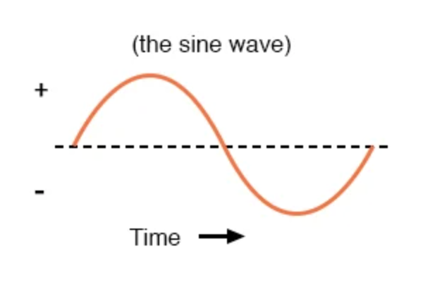
How do we know when the AC wave crosses 0, we use this to send a high pulse to 3011 (MOC) and depending on how much power we want the delay time of this pulse will be
AC = 220@60Hz
1/60 = 1.6x10^-3 seconds //For a complete wave
1.6x10^-3 s/2 = 8.3x10^-3 seconds // This is the time for a half cycle wave
0 seconds delay = 100% power
8.3x10^-3 seconds delay = 0% power
long dimerTime = int(map(val,0,100,8000,150));
        Timer1.attachInterrupt(gate,dimerTime);
        Timer1.start();
Material list:
1x Arduino pro mini, nano, etc
1x Moc 4n35
1x Moc 3011
1x Bt138
1x Diode bridge
1x Transformer 220v/110v to 12v - 5v
1x IR receiver
2x 220 ohms resistor
1x 330 ohms resistor
1x Led
Diagram:
https://easyeda.com/Death27/light_controller
EXPANDED TECHNICAL DETAILS
Remote Spectral Illumination Control
This project provides a professional-grade AC dimming solution that can be adjusted using any standard infrared (IR) remote.
- Zero-Cross Detection Interface: The Arduino monitors the AC mains' sine wave using an opto-isolated zero-cross circuit. This ensures the firmware can time the TRIAC firing pulses perfectly with the 50Hz/60Hz frequency, preventing flicker.
- IR Protocol Decoding: Captures IR signals via a TSOP38238 receiver. The Arduino decodes the HEX codes for "Volume Up" (Brighten) and "Volume Down" (Dim) and translates them into precise microsecond delays for the TRIAC trigger.
Safety
- Galvanic AC Isolation: Uses an opto-TRIAC (e.g., MOC3021) to provide a 5,000V electrical barrier between the Arduino logic and the high-voltage AC load, ensuring user safety.