Abstract
This tutorial is designed specially for “Digital Logic Board,” classified as an intermediate-level difficulty design, used as a training device for practicing purposes for new beginners in the electronics world, including concepts of important circuits in electronic logic.
Instead of old TTL “transistor-transistor logic” circuits, we use a Microchip microcontroller that can be programmed using an Arduino prototype board and the Arduino IDE.
The main topics of this project are learning logics, protocol timing, transferring data, and all of it deals with digital Boolean signals.
In the next pages, we explain a lot of concepts about this project:
- The slave Arduino board on the left powers up the LED by using a 4-byte data frame sent by the Master Arduino and controls the 74HC595 IC directly.
- The 2-wire SDA and SCL synchronize the byte stream between two Arduinos using the I2C protocol.
- The main Arduino board on the right reads the switch states and decides to send a single bit through an I2C Bus with a 4-byte frame data message.
Video
Silicon Foundations: Interactive Digital Logic Board
Before C++; before variables, arrays, and complex loops; everything in computing relies upon fundamental transistor physics known as Logic Gates (AND, OR, NOT, XOR). The Digital Logic Board project is an incredible educational testing rig! Instead of writing code, you physically plug massive 7400-series TTL (`Transistor-Transistor Logic`) Integrated Circuits into a test bench, utilizing physical tactile switches for `INPUTS` and massive LEDs for `OUTPUTS` to literally "feel" Boolean Algebra happening at the speed of light!
Evaluating The Truth Table Physically
An `AND` gate (e.g., the 74HC08 IC) requires exactly TWO inputs to be `HIGH (5V)` for the output to activate.
- The logic board features two massive Push Buttons (A and B).
- Both buttons have absolute 10K-Ohm Pull-Down resistors forcing a stable `LOW (0V)` into the gate when ignored.
- The output pin of the chip drives a 330-Ohm safeguarded red LED.
- The Execution: You push Button A (Nothing happens). You push Button B (Nothing happens). You violently press Both buttons simultaneously... The internal transistor architecture evaluates the `A & B` matrix, and the Red LED blasts on!
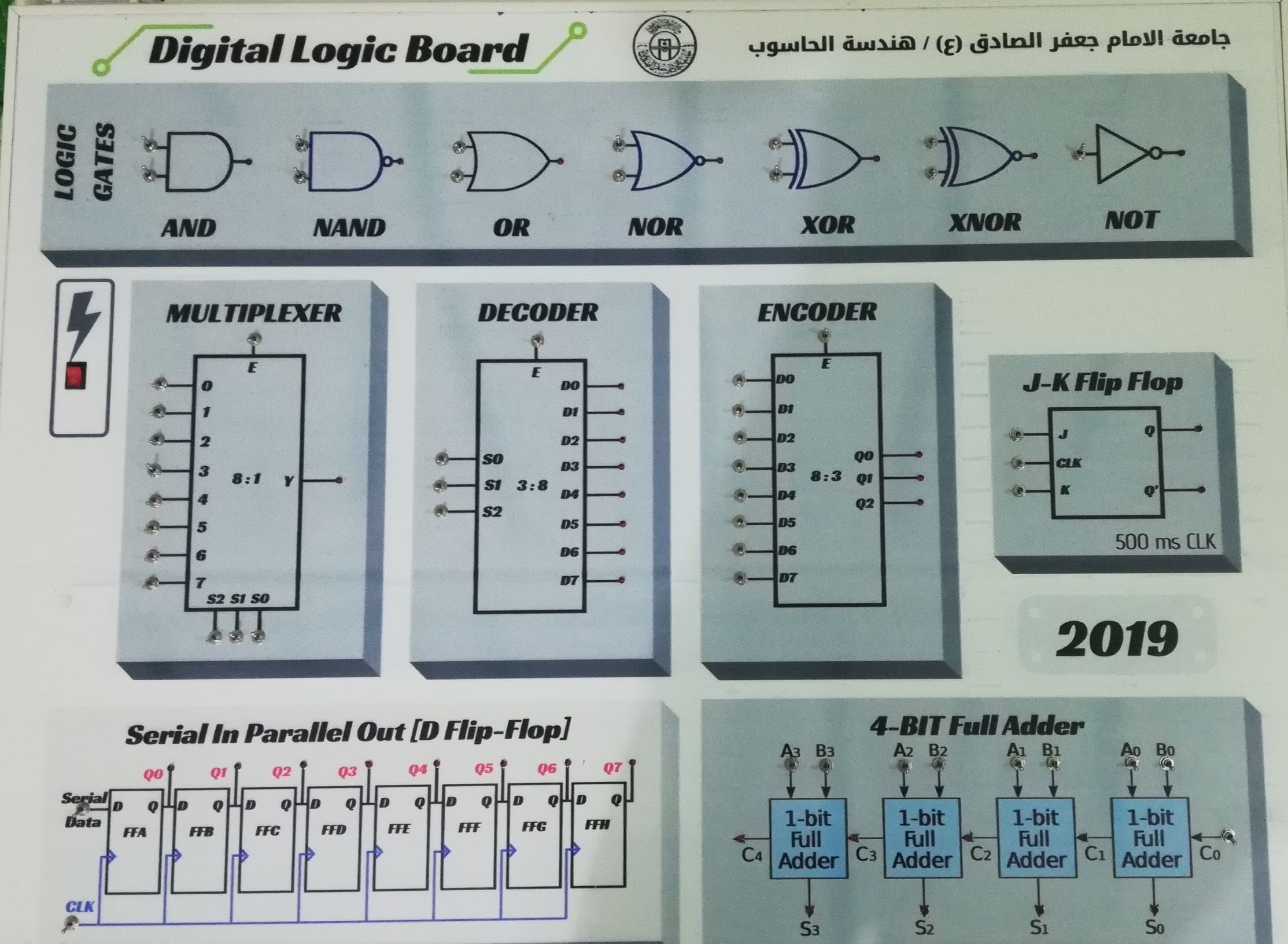
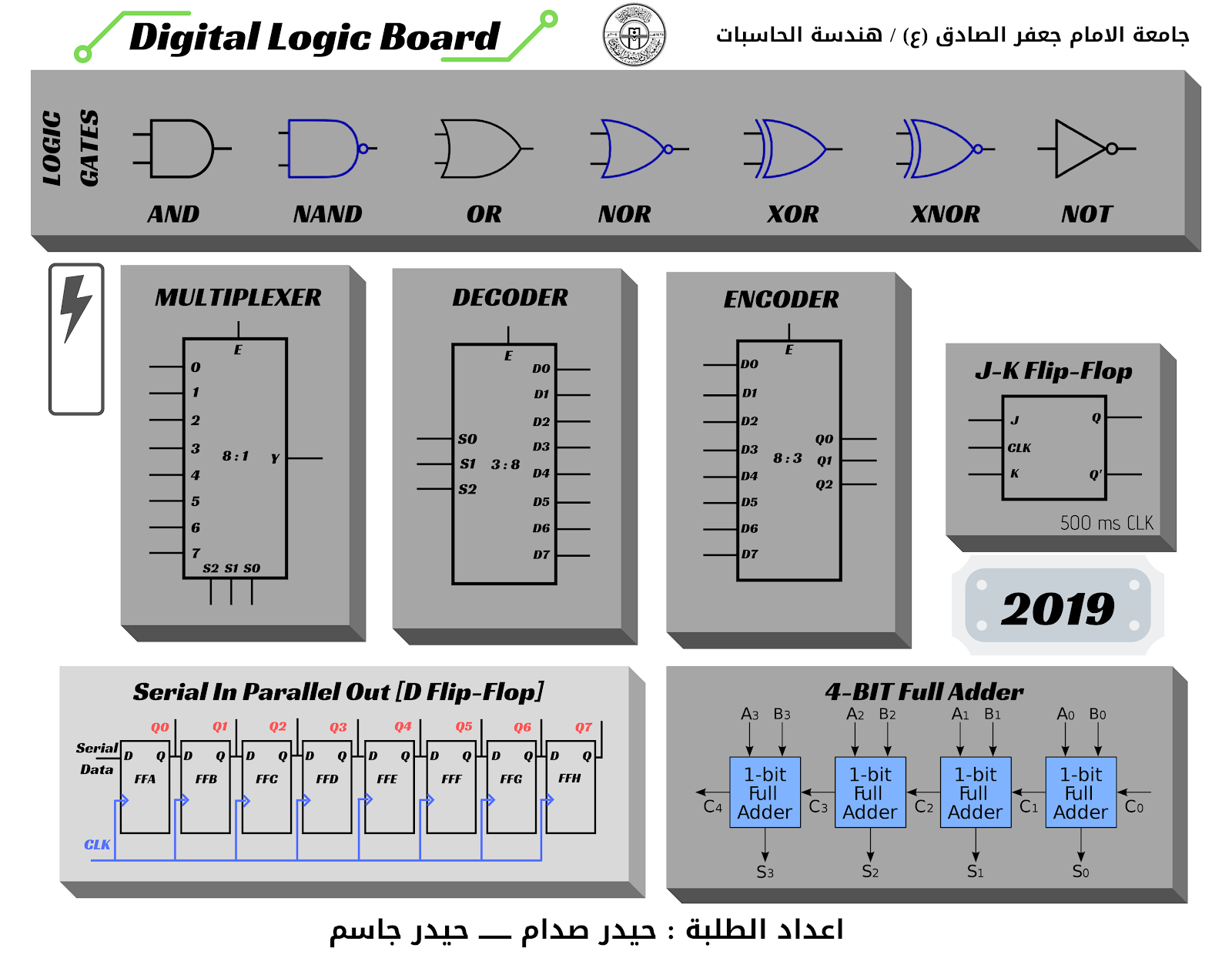
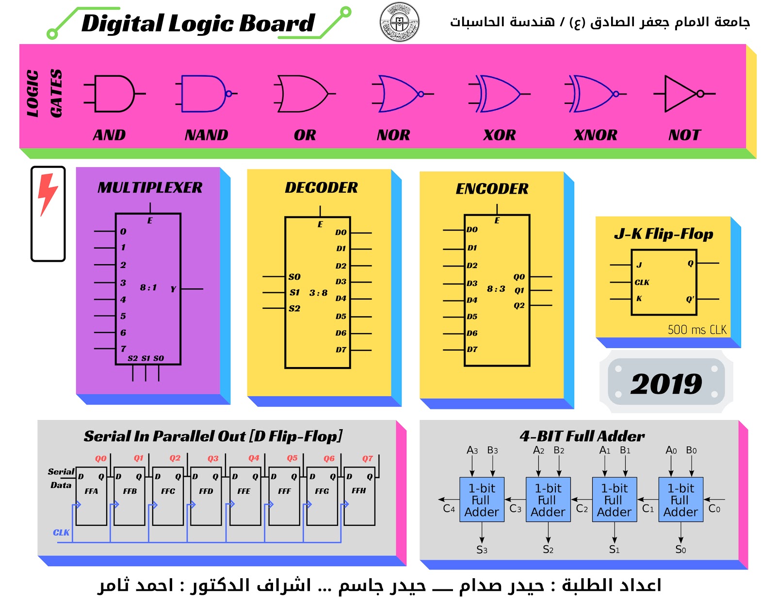
The Front Interface
From Top to Down Arrow
- 7 Logic Gates
- DC Power Switch
- 8-bit Multiplexer
- 8-bit Decoder
- 8-bit Encoder
- J-K Flip Flop
- SIPO shift register
- 4-Bit full adder
- Student name
Constructing The Testing Deck
There is no Arduino programming here. This project is about raw copper routing to provide a clean environment for testing delicate chips dynamically.
- Stable 5V Power Rails: An LM7805 voltage regulator guarantees the gates receive pristine 5.0V. Surging 9V directly into a 7400-series chip will instantly crack the silicon die.
- ZIF (Zero Insertion Force) Socket: The absolute best approach is using a heavy green ZIF socket. The user drops a mystery logic gate inside, locks the lever, and maps the logic physically to deduce if the chip is a `NAND` or `XOR` gate without bending pins!
- Debouncing Capacitors: 0.1µF ceramic capacitors are often wired across the power rails of the IC to stabilize voltage drops during rapid switching (Bypass Capacitors).
Graphic Design platform
Canva is a graphic design tool website, founded in 2012. It uses a drag-and-drop format and provides access to over a million photographs, graphics, and fonts. It is used by non-designers as well as professionals. The tools can be used for both web and print media design and graphics.

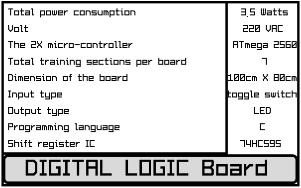
Quick Specification of the Board
Playground with Board
- First of all, you need to power up the board by using the Rocker Switch.
- To make a change for input logic, move the Toggle Switch.
- If the logic is true, then the RED LED will illuminate.
- In this case, you need to learn the Truth Table of every single circuit.
- The Logic Gates are (AND, NAND, OR, NOR, XOR, XNOR, NOT).
- Multiplexer
- Decoder, Encoder
- J-K Flip Flop
- Shift Register
- 4-Bit Full Adder
Fundamental Testing Hardware
- A Massive Breadboard or Custom PCB.
- A massive collection of 7400-series Logic ICs (`74HC00 NAND`, `74HC02 NOR`, `74HC04 NOT`, `74HC08 AND`, `74HC32 OR`, `74HC86 XOR`).
- Tactile Switches / SPDT Toggles for rigid Input 0/1 manipulation.
- LEDs and Current Limiting Resistors.
- Regulated 5V Power supply (E.g., MB102 Breadboard Power Supply Module).
L7805 Regulator
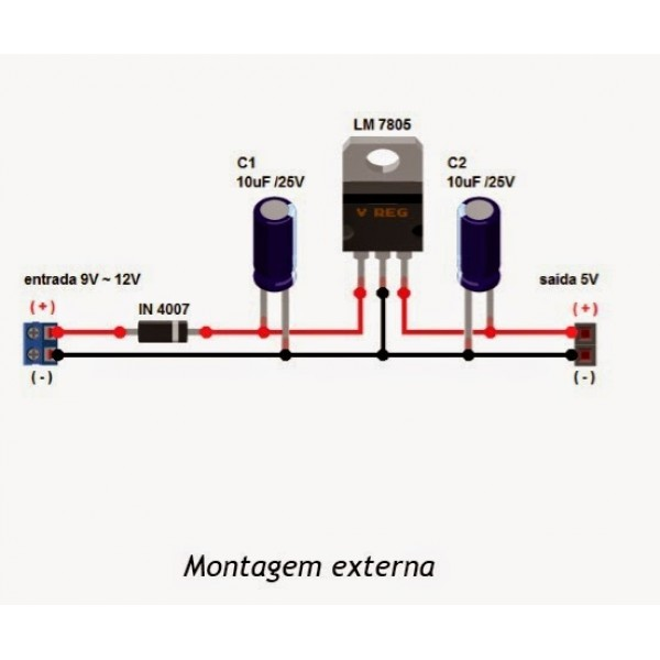
This device may take a 1.5 Volt as a drove voltage, so you must supply it with a minimum of 8 volts or more for power-hungry purposes.
Be careful to connect your PC while the 9-volt is alive!
That may destroy your battery inside!
Pull-up Resistor
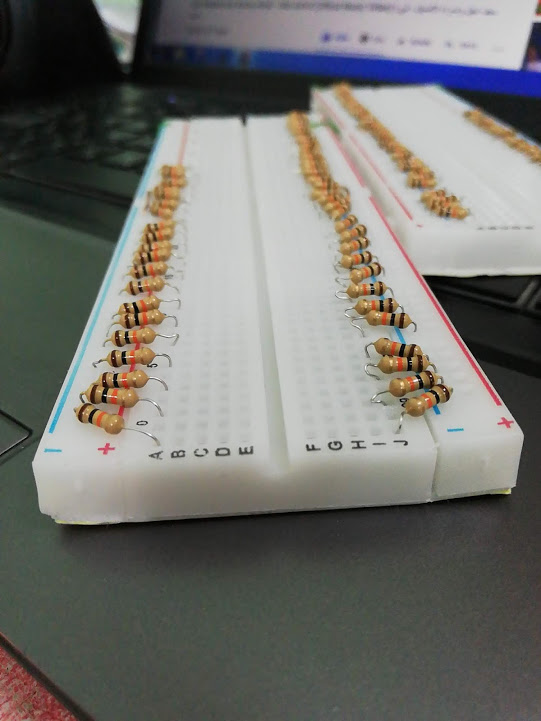
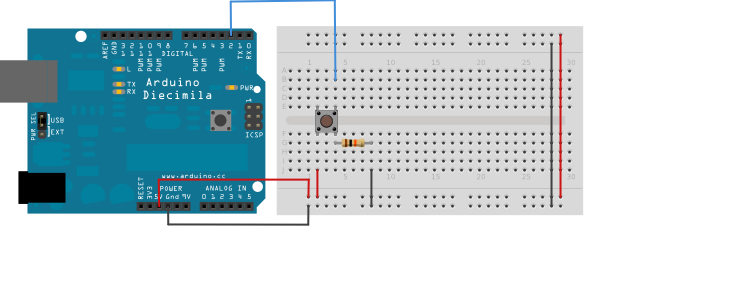
How to Connect on Breadboard
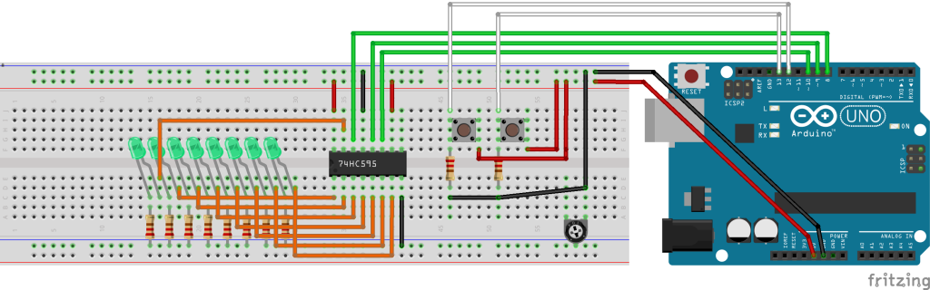
74HC595 Serial in Parallel Out Shift Register
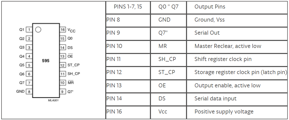
74HC595 SIPO Shift Register Connect to Arduino
74HC595 SIPO Shift register connect to Arduino
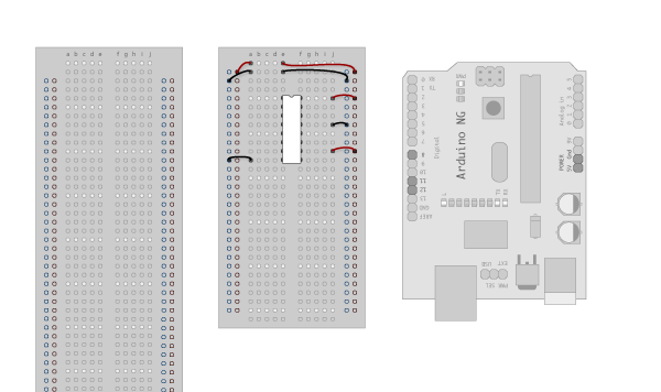
1. Make the following connections:
GND (pin 8) to ground,
Vcc (pin 16) to 5V
OE (pin 13) to ground
MR (pin 10) to 5V
This setup makes all of the output pins active and addressable all the time. The one flaw of this setup is that you end up with the lights turning on to their last state or something arbitrary every time you first power up the circuit before the program starts to run. You can get around this by controlling the MR and OE pins from your Arduino board too, but this way will work and leave you with more open pins.
2. Connect to Arduino

DS (pin 14) to Arduino DigitalPin 11 (blue wire)
SH_CP (pin 11) to Arduino DigitalPin 12 (yellow wire)
ST_CP (pin 12) to Arduino DigitalPin 8 (green wire)
From now on, those will be referred to as the dataPin, the clockPin, and the latchPin respectively.
Notice the 0.1"f capacitor on the latchPin; if you have some flicker when the latch pin pulses, you can use a capacitor to even it out.
3. Add 8 LEDs
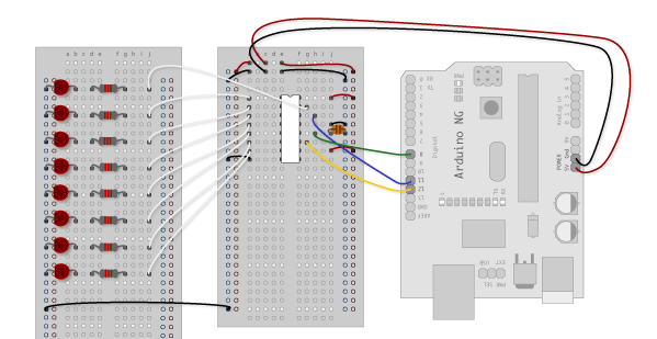
In this case, you should connect the cathode (short pin) of each LED to a common ground, and the anode (long pin) of each LED to its respective shift register output pin. Using the shift register to supply power like this is called sourcing current. Some shift registers can't source current; they can only do what is called sinking current. If you have one of those, it means you will have to flip the direction of the LEDs, putting the anodes directly to power and the cathodes (ground pins) to the shift register outputs. You should check your specific datasheet if you aren't using a 595 series chip. Don't forget to add a 470-ohm resistor in series to protect the LEDs from being overloaded.
Our 74HC595 Design
Pinout for Arduino Mega 2560
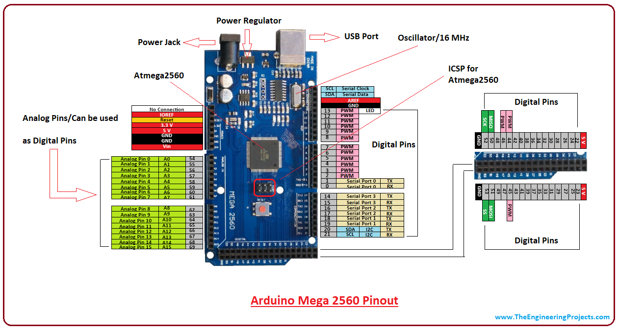
I²C on Arduino Mega 2560
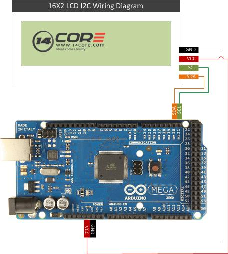
Serial Data Line (SDA) and Serial Clock Line (SCL) on Atmel Mega Arduino board
- SDA (Pin 20)
- SCL (Pin 21)
***Back End***
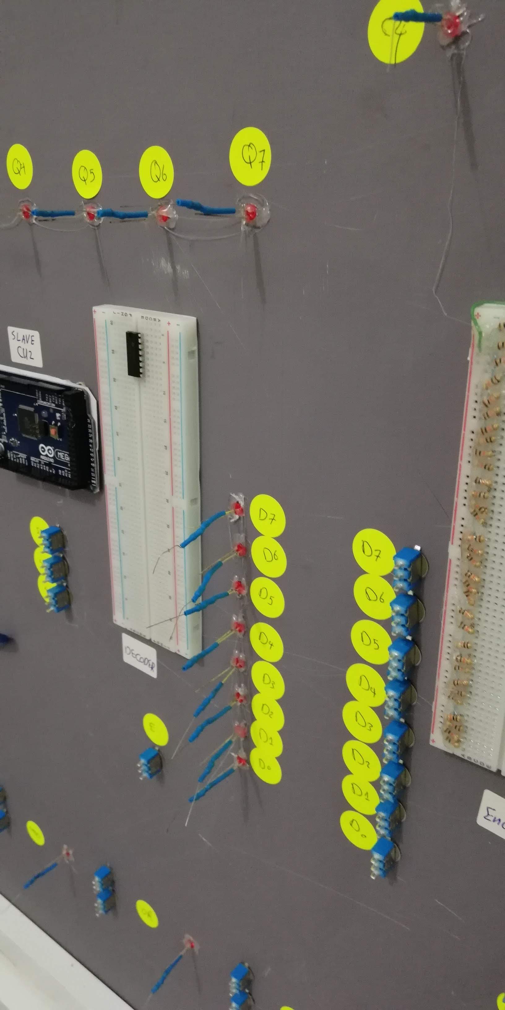
Final Result