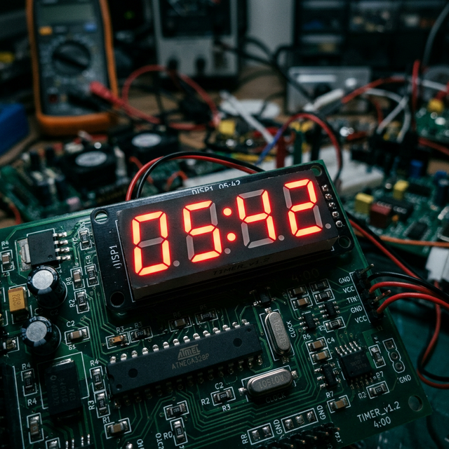
Temporal Matrix Displays: The Digital Wall Clock
Counting seconds utilizing delay(1000) inside an Arduino loop guarantees complete temporal collapse; within two days, your clock will drift extensively due to thermal oscillations acting upon the internal silicon oscillator. A completely reliable Digital Wall Clock must execute independent physical architecture! The Arduino queries an extreme-precision temperature-compensated hardware DS3231 RTC chip over the I2C bus, and immediately pipelines those exact epoch values into a massive MAX7219 driver, lighting up intense multiplexed 7-segment LED arrays large enough to track from across a large gymnasium!
The Absolute Standard: DS3231 Hardware RTC
The older DS1307 drifts radically if the room gets hot. The DS3231 is an elite Silicon-Oscillator containing its own internal thermometer to explicitly compensate for crystal frequency shift!
- The incredibly exact
<RTClib.h>library commands the physical chip natively via theA4andA5(SDA/SCL) bus. - The RTC keeps ticking utilizing a CR2032 backup button cell even if the primary 5V grid power fails completely!
DateTime now = rtc.now(); // Pull the absolute hardware Time array!

int h_time = now.hour();
int m_time = now.minute();
int s_time = now.second();

// Format it into a 4-digit number (e.g., 14:05 becomes 1405)!
int displayValue = (h_time * 100) + m_time;

display.showNumberDecEx(displayValue, (0x80 >> 1), true); // Blast to the 7-Seg LED!
MAX7219 and TM1637 Display Shift Registers
Wiring an 8-digit 7-segment display manually directly to an Arduino requires 64 separate wires and infinitely complex software-polling loops.
- You must mandate a MAX7219 or TM1637 Shift Register Display Module!
- These incredibly robust integrated chips take over the brutal task of multiplexing the LEDs independently.
- The Arduino utilizes a complex high-speed
SPIinterface, dumping just four wires into the display: "Put the number 9 on Position #2!" and the chip violently maintains that LED state so the Arduino can go to sleep!
Chronometry Assembly Architecture
- Arduino Nano (The ultra-compact Nano easily mounts behind the large LED array panels).
- DS3231 I2C Real Time Clock Module (CR2032 Lithium battery is absolutely critical for power-failure survival!).
- Large MAX7219 / TM1637 7-Segment LED display panels (Often chain-linked to show Hours, Minutes, and explicit Seconds seamlessly).
- Physical "Set Time" Tactile Buttons (Wired to Digital Pins with
INPUT_PULLUPto allow manual Daylight Savings time adjustment arrays without reconnecting a laptop). - Massive 5V Power Supply (If updating gigantic 4-inch tall 7-Segment Matrix modules, the Arduino's USB port will violently overheat. Supply 2Amp+ 5V natively!).