Introduction
Cycling has become a significant part of my life, and I choose to bike to school whenever I can. However, signaling turns has always been a challenge for me, especially with the amount of cars on the road. To fix this issue, I came up with an idea: attaching direction indicators to my bike. To signal a right turn, all you have to do is push the button on the right side of your handlebar, and for a left turn, push the button on the left side. The idea is to make signaling as easy as a press of a button, eliminating the need to take a hand off the handlebar in the middle of traffic.
Hand signals during nighttime urban cycling are completely invisible to fast-moving cars, inviting catastrophe. The Direction Indicator for Bike utilizes solid-state electronic switching to establish a massive, undeniable visual presence! Using an Arduino to orchestrate rapid, sequential "Audi-style" sweeping LED flashes, the rider commands Left or Right turning signals from dual handlebars switches, guaranteeing immediate optical recognition from trailing vehicles through thick fog or rain.
Step 1: Design
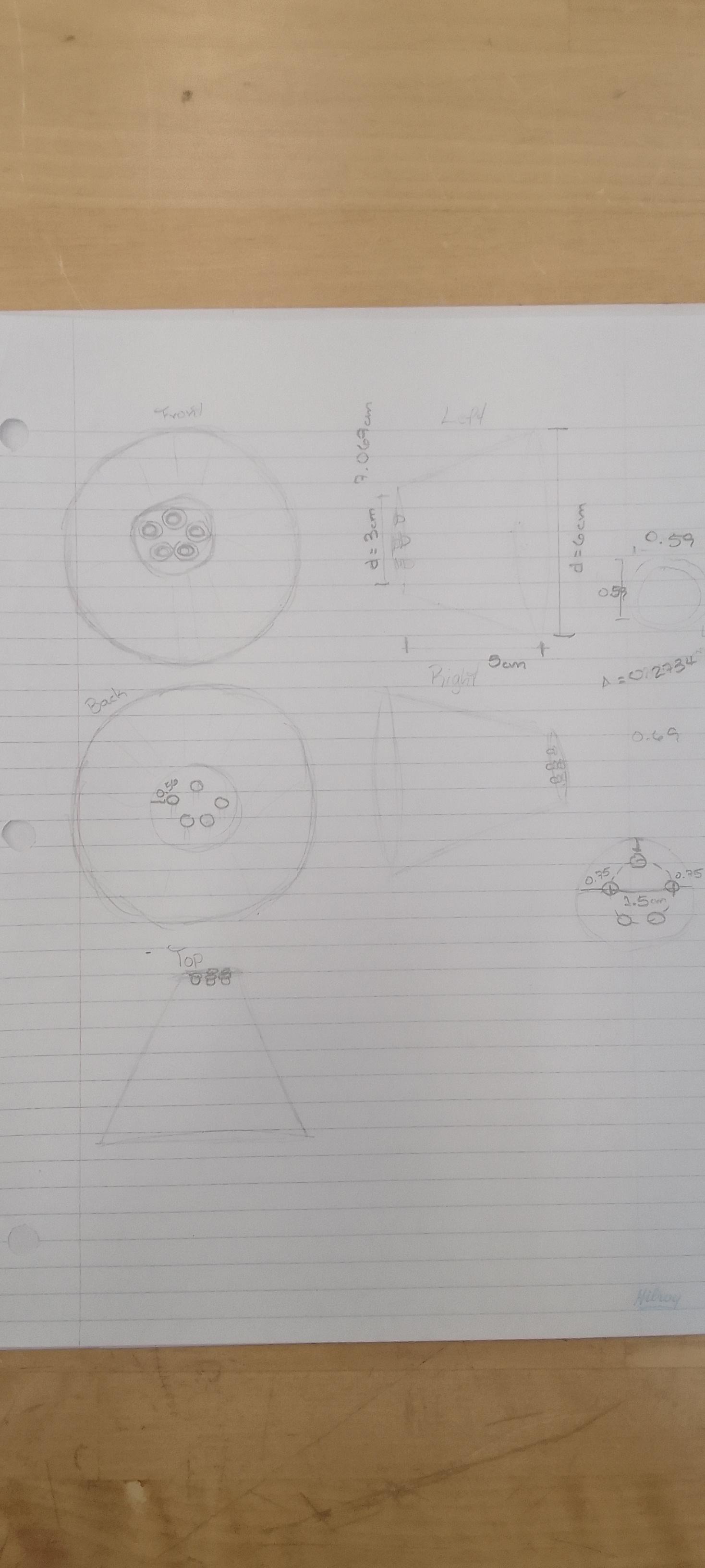
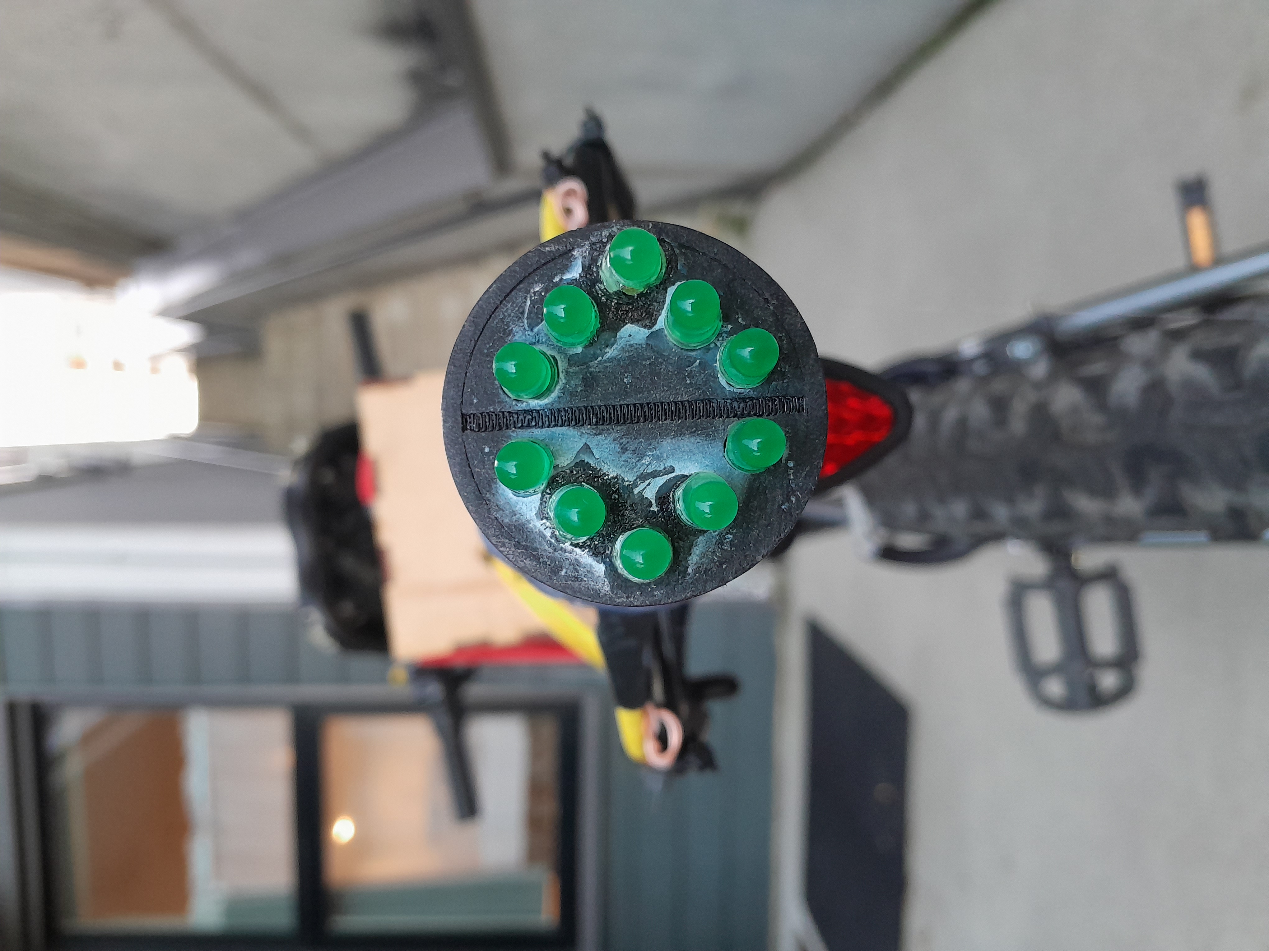
I decided to put the LED direction indicators at the luggage carrier. At this place the direction indicators will be good to see if you're in a car behind me. I decided to attach the Arduino behind the LEDs on a laser-cut plywood box and the push buttons to the handlebar with 3d printed parts that fit my bike. These 3D parts had to be designed to perfectly match the dimensions of my bike, and I created an orthographic projection to visualize their appearance and dimensions.
Step 2: 3D Design and Printing
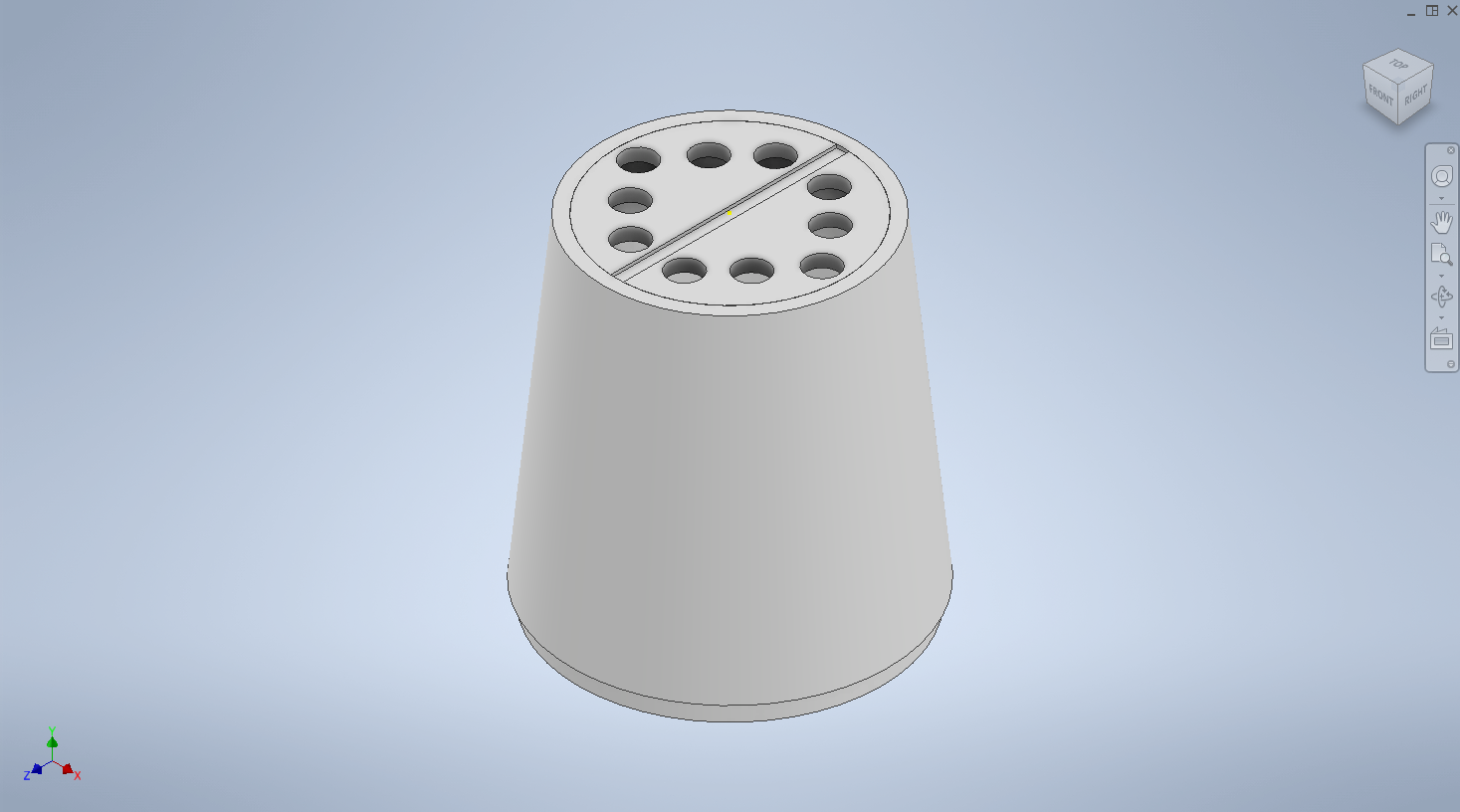
Using Autodesk Inventor, I created 3D designs for the components. Once I was done with the designs, I proceeded to 3D print the components on a Tinkerine Ditto Pro 3D Printer.
Step 3: Laser Cutting
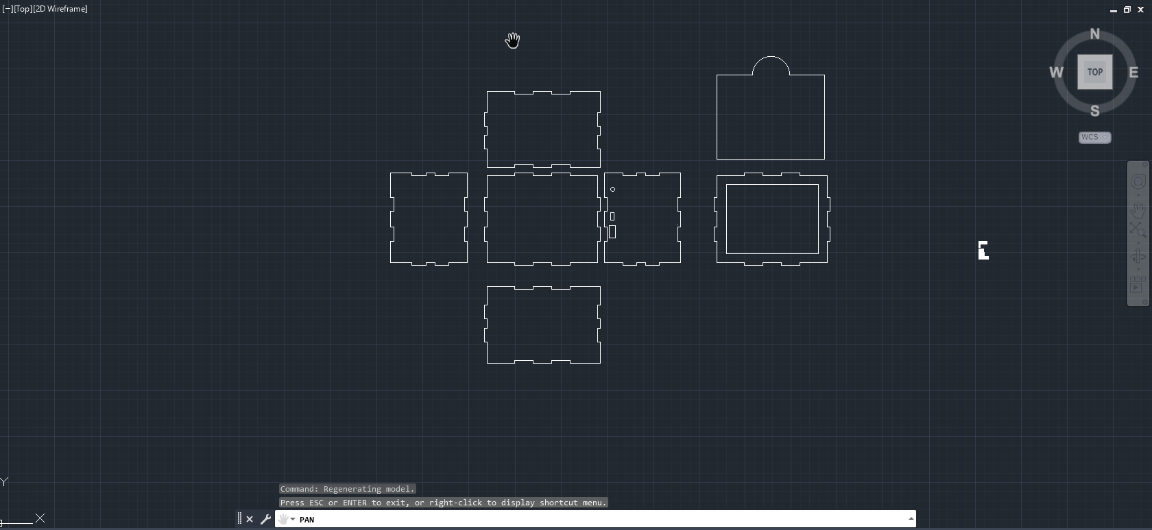
- Using AutoCAD, I created a drawing for the plywood box. For the box, I decided for a sliding lid since it will give me the least problems and it's easy to make. As well as, holes for the power bank connection to the Arduino. Once I was done with the drawing, I proceeded to laser-cut the drawing on a Trotec Speedy 100 Laser.
- I used wood glue on each finger to connect each piece of the box.
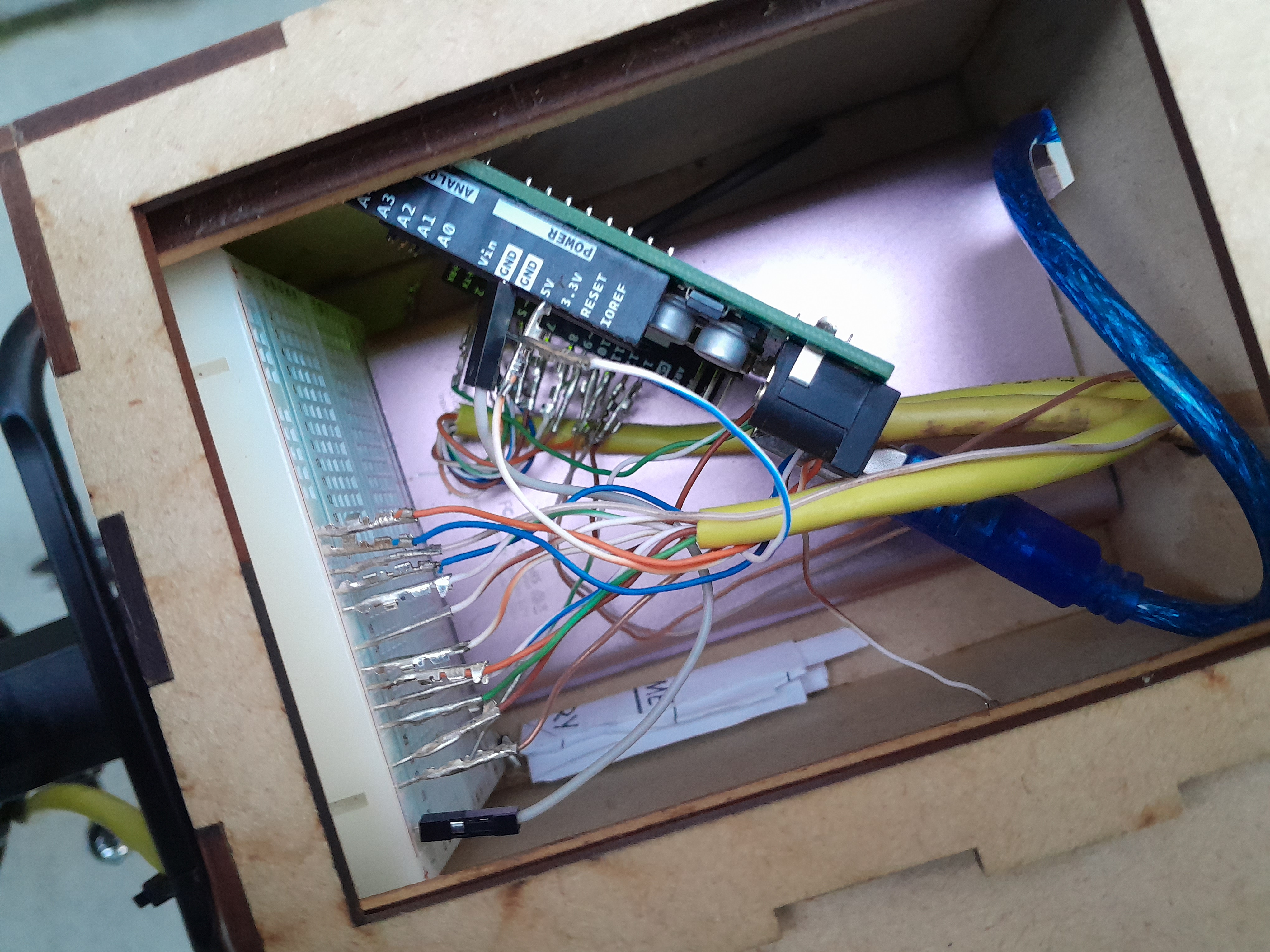
Step 4: Wiring
- Glue the Mini Breadboard to the side of the plywood box.
- Put the Arduino in the plywood box.
- Put the Power Bank in the plywood box. Connect the USB cable to the Arduino.
- Solder the 470 Ohm resistor to the cathode and wires to the end of the resistor and the anode for each of the LEDs. Add heat-shrinking tubes to the soldered connections.
- Crimp pins to the end of the wire of each of the LEDs.
- Attach the anode LED wires to the data pins of the Arduino (Left LEDs: 12,11,10,9,8; Right LEDs: 7,6,5,4,3)
- Attach the cathode LED wires to the Mini Breadboard so that they all connect.
- Attach a wire from the connected cathode LED wires to the ground (GND) of the Arduino
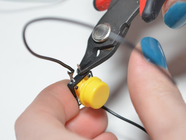
- Solder 2 wires to one side of each the buttons. Opposite to the wire you decide to attach to ground in the Arduino, solder the 10k Ohm Resistor and a wire to the end of it. Add heat-shrinking tubes to the soldered connections.
- Crimp pins to the end of the wire of each of the buttons.
- Attach the Button pins (the wire that is opposite to the ones next to each other) to the data pins of the Arduino (Left Button: 13; Right Button:2)
- Attach the Button wire (the wire you decided to attach to ground in the Arduino) to the the cathode LED wires connected to the Mini Breadboard.
- Attach the remaining Button wire to the 5V pin in the Arduino.
EXPANDED TECHNICAL DETAILS: The Switch Matrix and Pull-Up Resistance
If you wire a switch to an Arduino without a stable voltage anchor, the digital pin "Floats", behaving completely randomly due to atmospheric static!
- The Left and Right handlebar toggle switches are wired directly between Digital Pins (e.g., Pin 2 and 3) and GND.
- The Arduino MUST initialize internal pull-up resistors!
pinMode(LEFT_SWITCH, INPUT_PULLUP);- This locks the pins reliably at 5V. When the rider flicks the switch, it instantly shorts the pin to Ground, securely reading a
LOWstate!
void loop() {
  if (digitalRead(LEFT_SWITCH) == LOW) { // The rider wants to turn Left!
    // Execute a massive sequential sweeping blink array!
    for (int i=4; i<=7; i++) {
        digitalWrite(i, HIGH); // Light up LED array segment!
        delay(50);             // Sweep effect!
    }
    delay(200);
    // Turn them all off to reset the cycle!
    for (int i=4; i<=7; i++) { digitalWrite(i, LOW); }
    delay(200);
  }
}
EXPANDED TECHNICAL DETAILS: Expanding to Massive Addressable 12V LED Strips
A standard 5mm Arduino LED is useless to a truck driver 100 meters behind you.
- You must use extremely bright 12 Volt Yellow LED Strips or WS2812B NeoPixels!
- An Arduino CANNOT power 12V LEDs directly; you must use massive TIP120 Darlington Transistors or N-Channel IRLZ44N Logic-Level MOSFETs!
- The Arduino sends its weak 5V signal to the MOSFET "Gate", which acts as an electronic dam, instantly releasing massive 12V automotive battery current directly into the LED strips synchronously!
EXPANDED TECHNICAL DETAILS: Transport Illumination Hardware Elements
- Arduino Nano or Pro Mini (Tiny boards easily hidden inside the bicycle's under-seat wedge bag or PVC tubing).
- Physical Bar-End or Handlebar Switch Array (Must be heavily waterproofed against rain!).
- Super Bright Yellow LED Strips (WS2812B for complex animations, or 12V dumb RGB strips for extreme brightness output).
- Logic Level N-Channel MOSFETs (Critically mandatory to switch the severe amperage required to blind trailing cars).
- Hardened 18650 Li-Ion Battery Pack (To provide the intense burst current needed for maximum optical penetration over hours of riding).
Step 5: Attaching parts together and to my Bike
I used nuts, screws and bolts to attach each 3d part together and hot glue for the electronics parts that needed to be attached to the 3d printed parts:
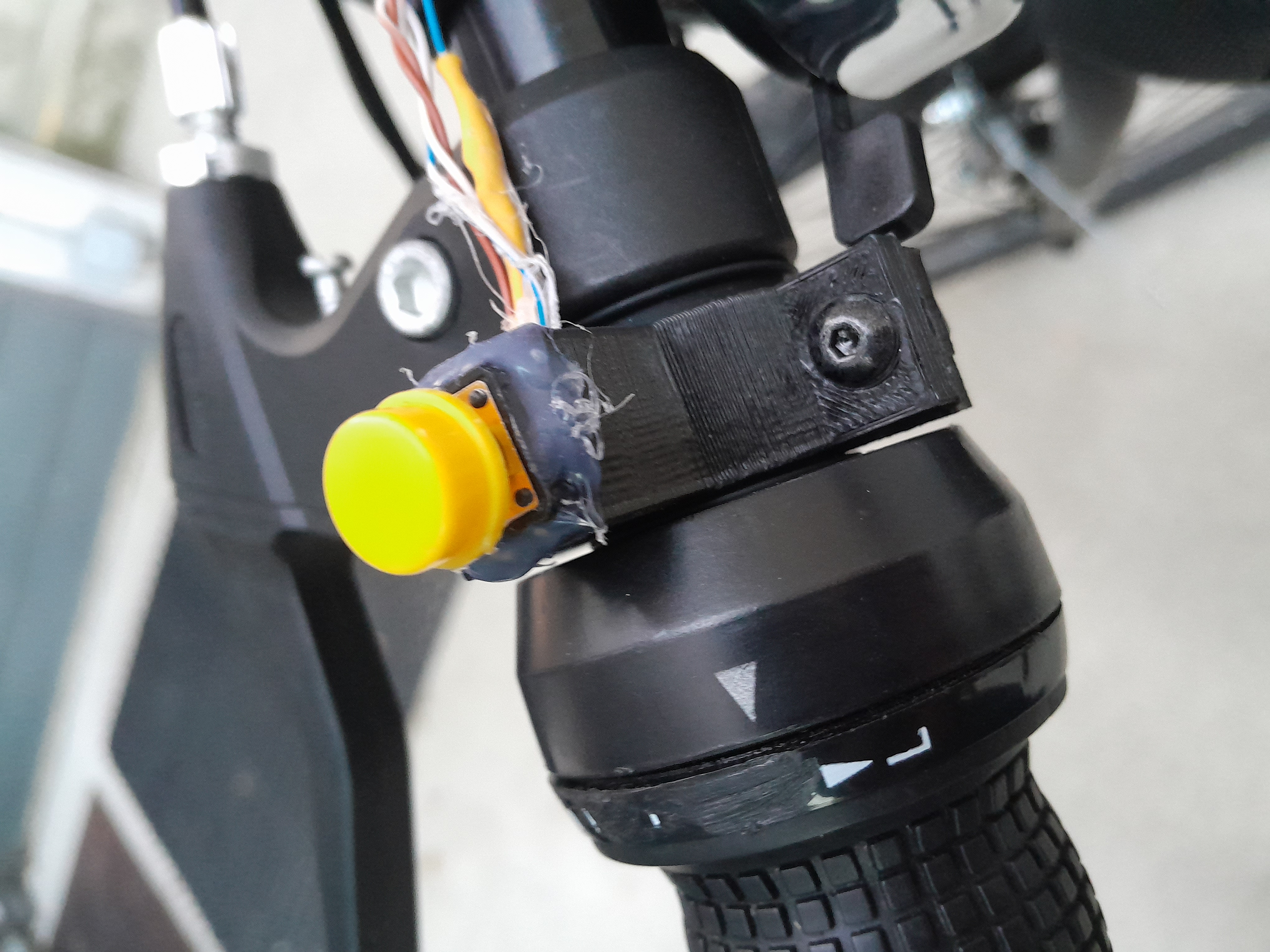
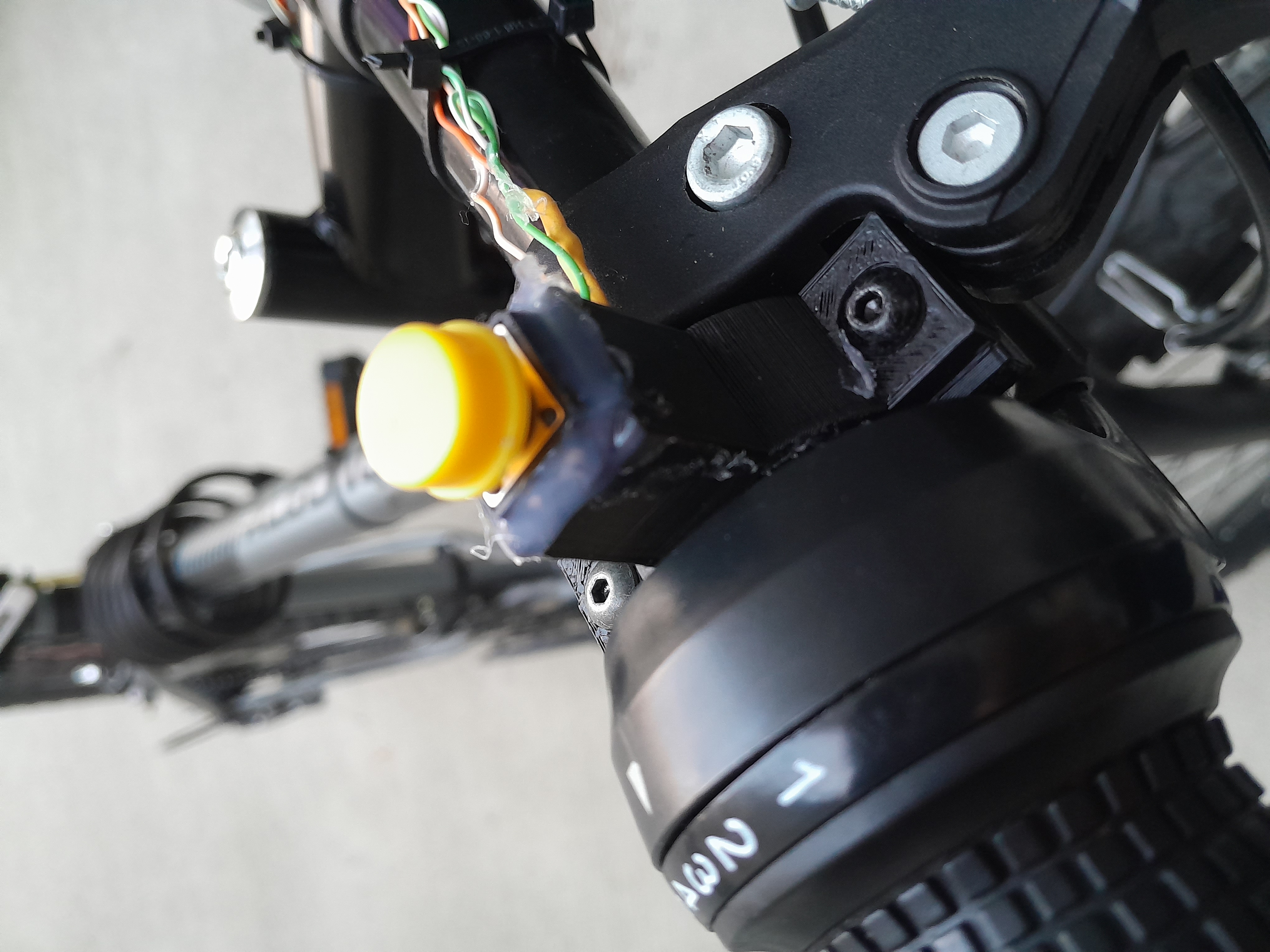
As for the long cables going from the buttons and LEDs to the Arduino, I tied them with zip ties to the bike.
Improvements/upgrades
- Make direction indicator on the same box as the Arduino.
- Make direction indicators at the front of your bike too.
- Better cable organization.