Hey peeps!
I am back with a new interesting project.
In this project I made a display board using a GSM module and Arduino Uno. In this project you can send the message from mobile phone to the SIM card which is in the GSM module and that message will be appeared on the display.
You can use this project as a display board at home or notice board in college. It can be used as a patient numbering system in hospitals where doctors can send the message displaying the number of the patient and that patient will come to the doctor.
Project Perspective
This Display Board is a sophisticated exploration of telecommunication technology and physical-to-digital interaction. By focusing on the essential building blocks—the GSM module and the Character LCD—you'll learn how to communicate and display information remotely using a specialized software logic and a robust wireless setup.
Technical Implementation: GSM AT-Commands and SMS Parsing
The project reveals the hidden layers of simple SMS-to-display interaction:
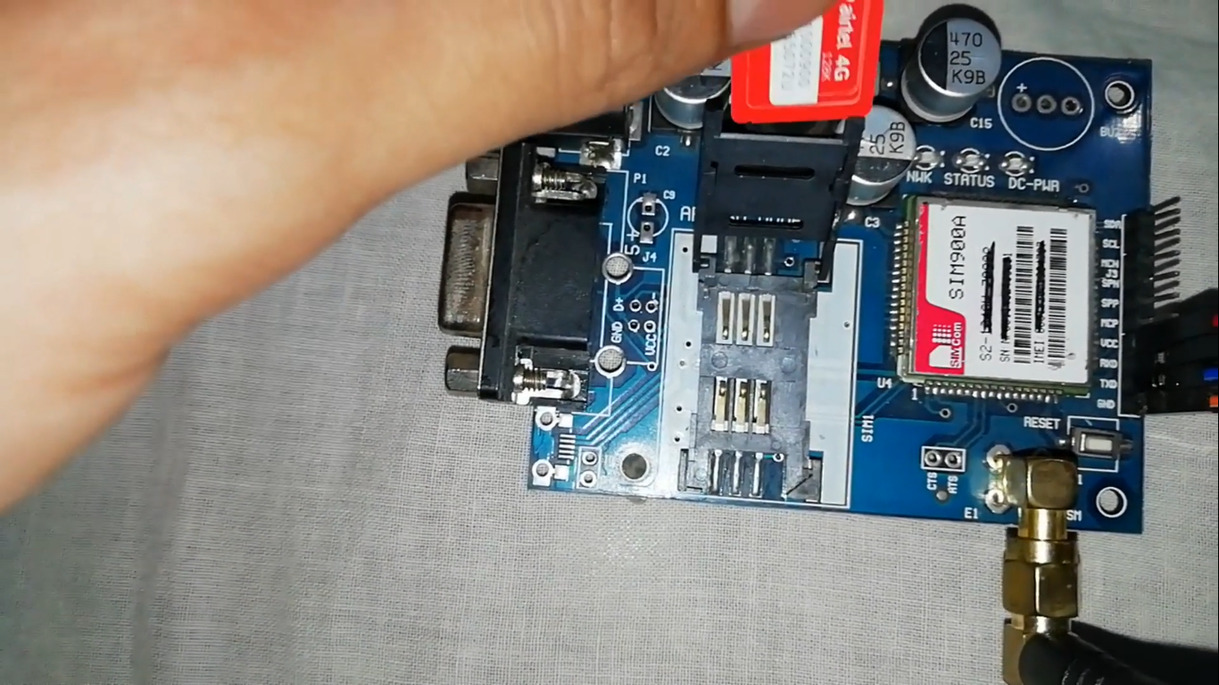
- Identification layer: The SIM800L GSM Module acts as a wireless eye, receiving text from your smartphone via the carrier network.
- Conversion layer: The Arduino uses its Serial (TX/RX) interface to receive and interpret high-speed AT-commands to coordinate message tasks.
- Visual Interface layer: A 16x2 LCD Display provides the high-definition visual output for your SMS status (e.g., "Message Received").
- Processing Logic layer: The Arduino code follows a "serial timing" strategy: it interprets incoming
+CMTsignals and matches the character buffer to provide a safe and accurate remote display. - Communication Dialogue Loop: Data is sent to the Serial Monitor during initial calibration to coordinate status.
Hardware-Mobile Infrastructure
- Arduino Uno: The "brain" of the project, managing multi-directional serial communication and coordinating LCD output.
- GSM Module (SIM800L): Providing a reliable "Mobile Link" for the display board.
- 2G SIM Card: Providing cellular access for your remote mission.
- 12V 5A Power Supply: Essential for providing stable power for the GSM module's radio bursts.
- Alphanumeric LCD: Provides a clear and professional physical interface for your remote messages.
- Micro-USB Cable: Used to program the Arduino.
[!IMPORTANT] The GSM SIM800L module needs a strong and stable power supply during wireless connection; using the Arduino's 5V pin often causes resets!
Let's get started to make this project:
Steps:
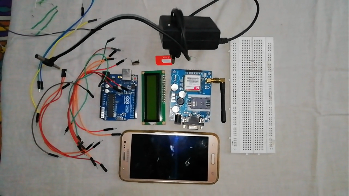
Gather all the components.
Connect pot and LCD display on breadboard
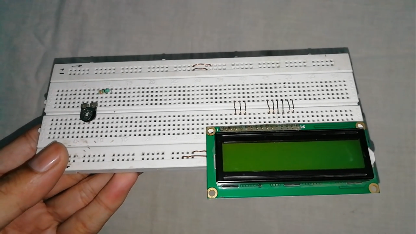
Connect a 330 ohm resistor to second end of pot.
Connect all components as shown.
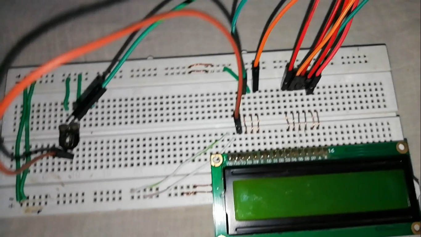
Connections are below:
- LCD TO ARDUINO
- Vss -> GND
- Vdd -> +5v
- Vo -> middle end of pot
- Rs -> Pin 3
- Rw -> GND
- E -> Pin 4
- D4 -> Pin 5
- D5 -> Pin 6
- D6 -> Pin 7
- D7 -> Pin 8
- A -> one end to resistor 330 ohm to pot and that end to +5v
- K -> one end to pot and that end to GND
- LCD TO ARDUINO
Connect GSM module with M-F jumper wires as shown.
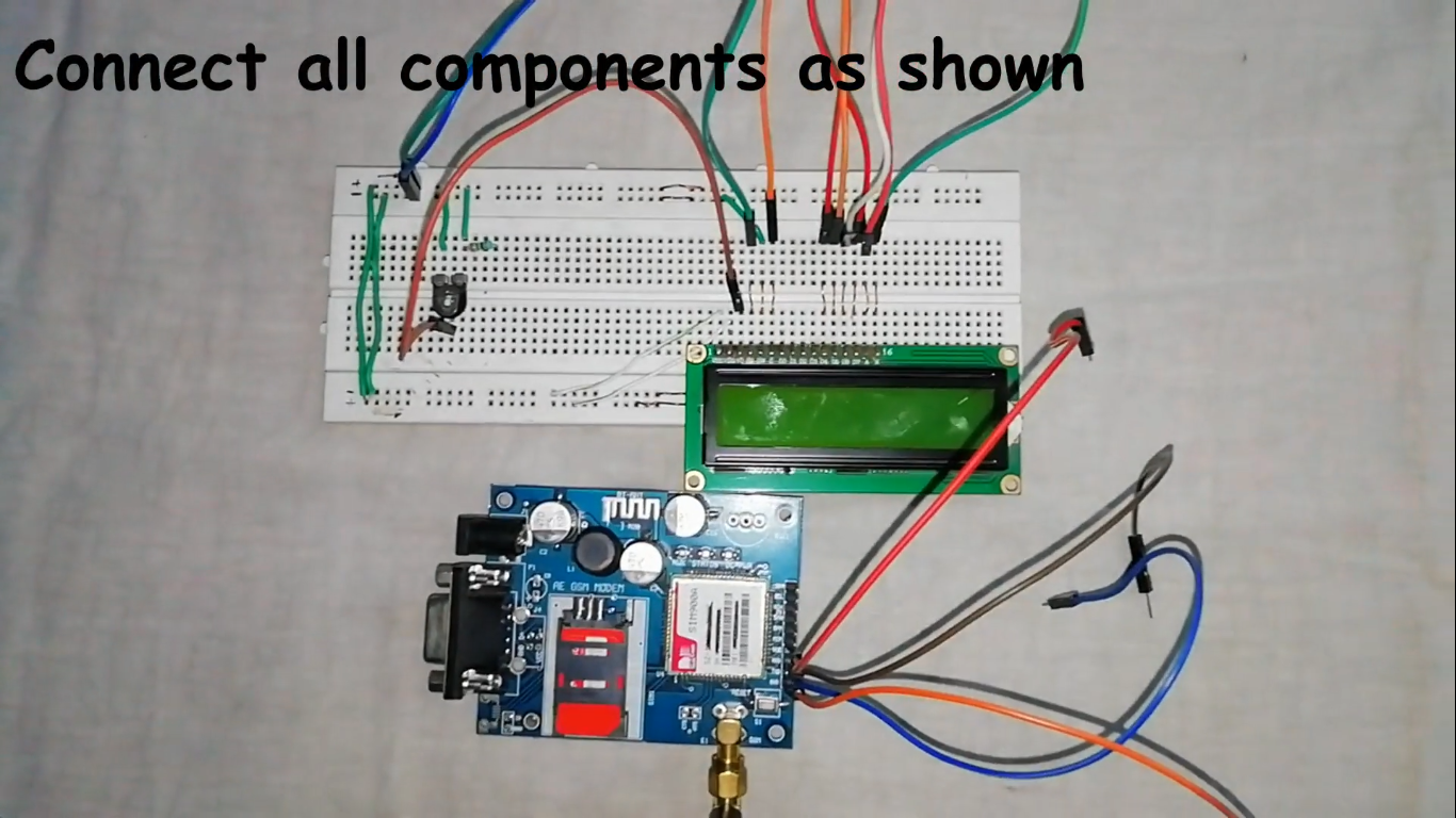
Insert sim in the GSM module (preferably 2G SIM).
Connections:
- GSM module to Arduino
- Vcc -> +5v
- Gnd -> GND
- Tx -> Rx
- Rx -> Tx
- Make sure that Tx and Rx pins of the GSM module are disconnected while uploading the code. After uploading the code, connect the Tx and Rx pins of the GSM Module to the Arduino.
- GSM module to Arduino
Integration and Interaction Step-by-Step
The GSM display process is designed to be very efficient:
Initialize Hardware: Correctly seat the GSM module and the LCD on the breadboard and insert the SIM card.
Setup Output Sync: In the
setup()function, initialize theSoftwareSerialobject and define the LCD character size.Execution Loop: The board constantly performs high-performance SMS checks and updates the display in real-time based on your phone's message.
Visual and Data Feedback Integration: Watch your custom dashboard and the LCD automatically become a rhythmic visual signal, pulsing and following your text settings in the room.
Now take a smart phone and send the message to that number followed by # and end by * as shown.
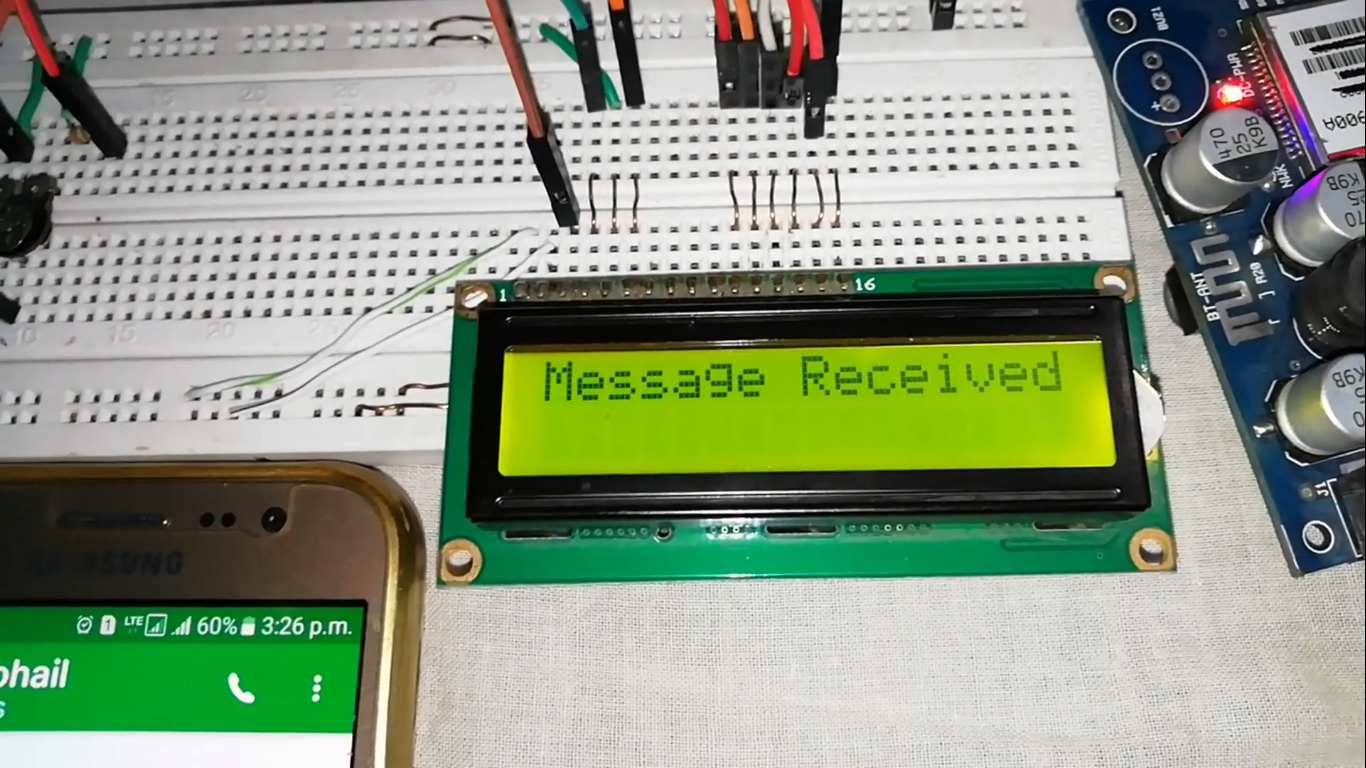
Message will be received.
Cheers, your project is done!
Future Expansion
- OLED Identity Dashboard Integration: Add a small OLED display to the board to show "Signal (dBm)" or the "Carrier Name."
- Multi-sensor Climate Sync Synchronization: Connect a specialized "Thermistor" to perform a "Current Temp" update alongside the SMS text.
- Cloud Interface Registration Support Synchronization: Add a specialized web-dashboard on your smartphone over WiFi/BT to precisely track and log the total SMS history.
- Advanced Velocity Profile Customization Support: Add a specialized "Security Whitelist" to the code to allow the board to display messages from specific phone numbers only.
Display Board is a perfect project for any science enthusiast looking for a more interactive and engaging telecomm tool!
Also, be sure to subscribe to my channel.
Thanks!