VIDEO TUTORIAL
A Shortcut to the World of Arduino for Beginners
Stepping into the world of Embedded Systems with an Arduino board often comes with daunting challenges, especially for those without prior C++ programming knowledge. When we try to combine multiple devices beyond basic Starter Kit projects, issues with Code Syntax and Logic frequently become major obstacles.
I had attempted to build this project several times without success until I discovered Visuino, a very powerful Visual Programming development environment for Makers. This software is designed to break down the coding barrier, allowing us to fully focus on Logic and the interaction of Physical Computing devices by placing Component blocks and drawing data connection lines instead of typing commands.
System Component Details and Operation
In this project, we focus on building an automated system that responds to its environment, featuring the following main devices:
- Arduino Board: Serves as the main "brain" for processing the Logic we design in Visuino.
- PIR Sensor (Passive Infrared Sensor): A motion detection sensor that works by measuring infrared radiation from warm objects (such as the human body). The sensor has a Fresnel lens to expand its detection range. When there is a change in the infrared level, a Digital Output signal is sent to the Arduino.
- Relay Module: Since Arduino operates at low voltage (5V DC) but we want to control larger electrical devices (e.g., AC lights), the Relay acts as an electromagnetic switch that helps isolate the low-voltage circuit from the high-voltage circuit for safety and efficient control.
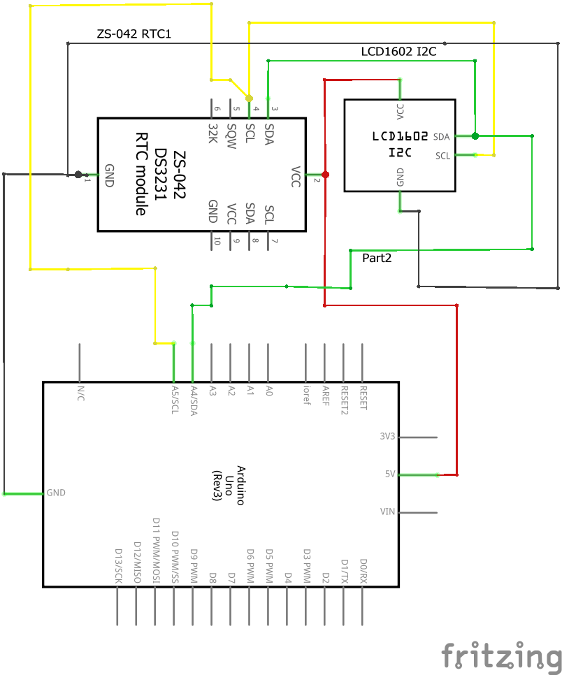
Circuit Diagram (Schematic)
Circuit design (Schematic) is the heart of any Hardware project. This project systematically allocates Input signals from the sensor and sends Output to the Relay module to ensure correct current flow and minimize signal interference.
Layout & Control Logic
The internal operational Logic in Visuino is simple yet effective:
- Input Stage: A Digital Input block receives values from the PIR Sensor. When motion is detected, the status will be
True(High). - Processing Stage: We can add On/Off Switch or Pulse Generator blocks to specify how long the Relay should remain active after the sensor stops detecting motion.
- Output Stage: Data is sent to the Digital Output Pin connected to the Relay to "flip the switch" and activate the electrical appliance.

Using Visuino allows us to visualize the overall Data Flow from start to finish, making Debugging or future system improvements much easier, even if you have no prior Coding experience.