My son gave me this vfd48 display and I did not know what to do with it.
I searched on the internet for solutions, but there was none with arduino.
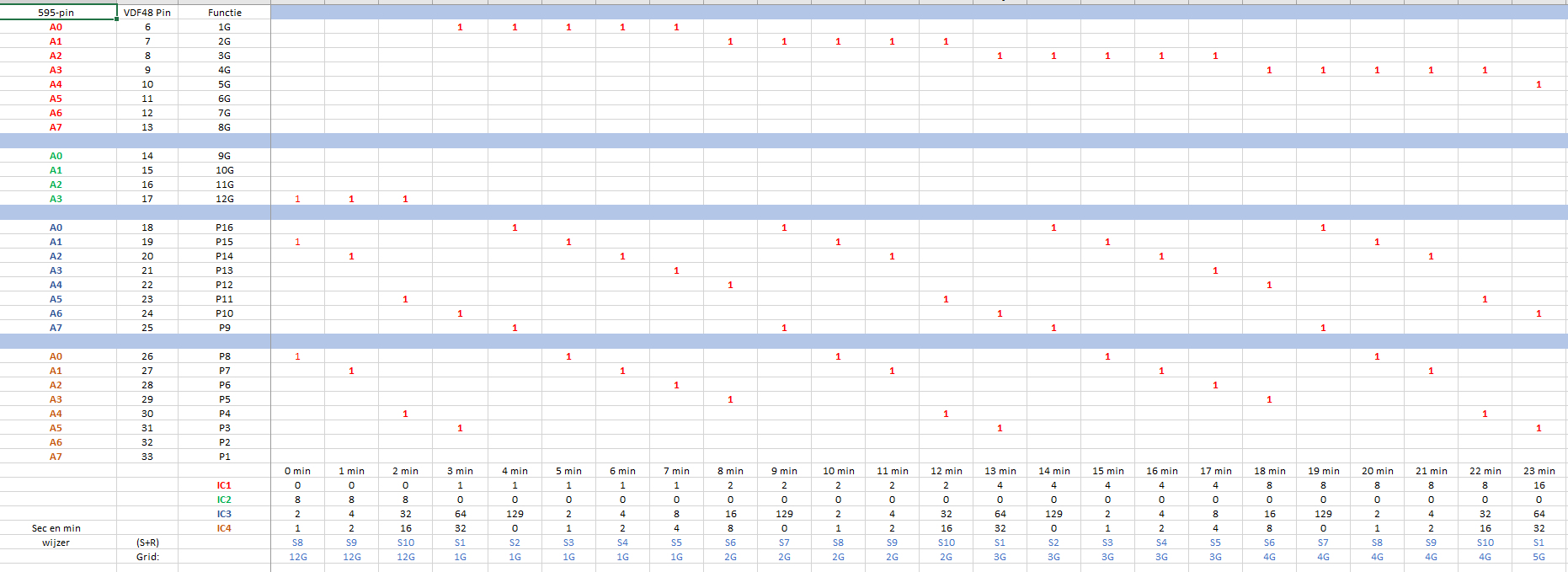
So a few months ago I decided to make the display to work. I downloaded the datasheet and made in excel an overview of all the commands to use.
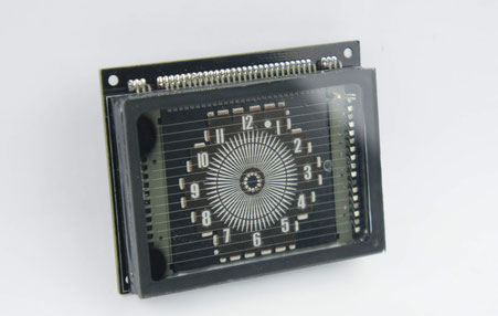
The datasheet says that the filamentvoltage is 2.4 VAC, but it works well with 1.5 VDC. I have measured the current of the filament, it was 280 mA. Also the grid and anode voltages should be 30 VDC, but it works fine with 20 VDC. It has 12 grids, 16 anodes.
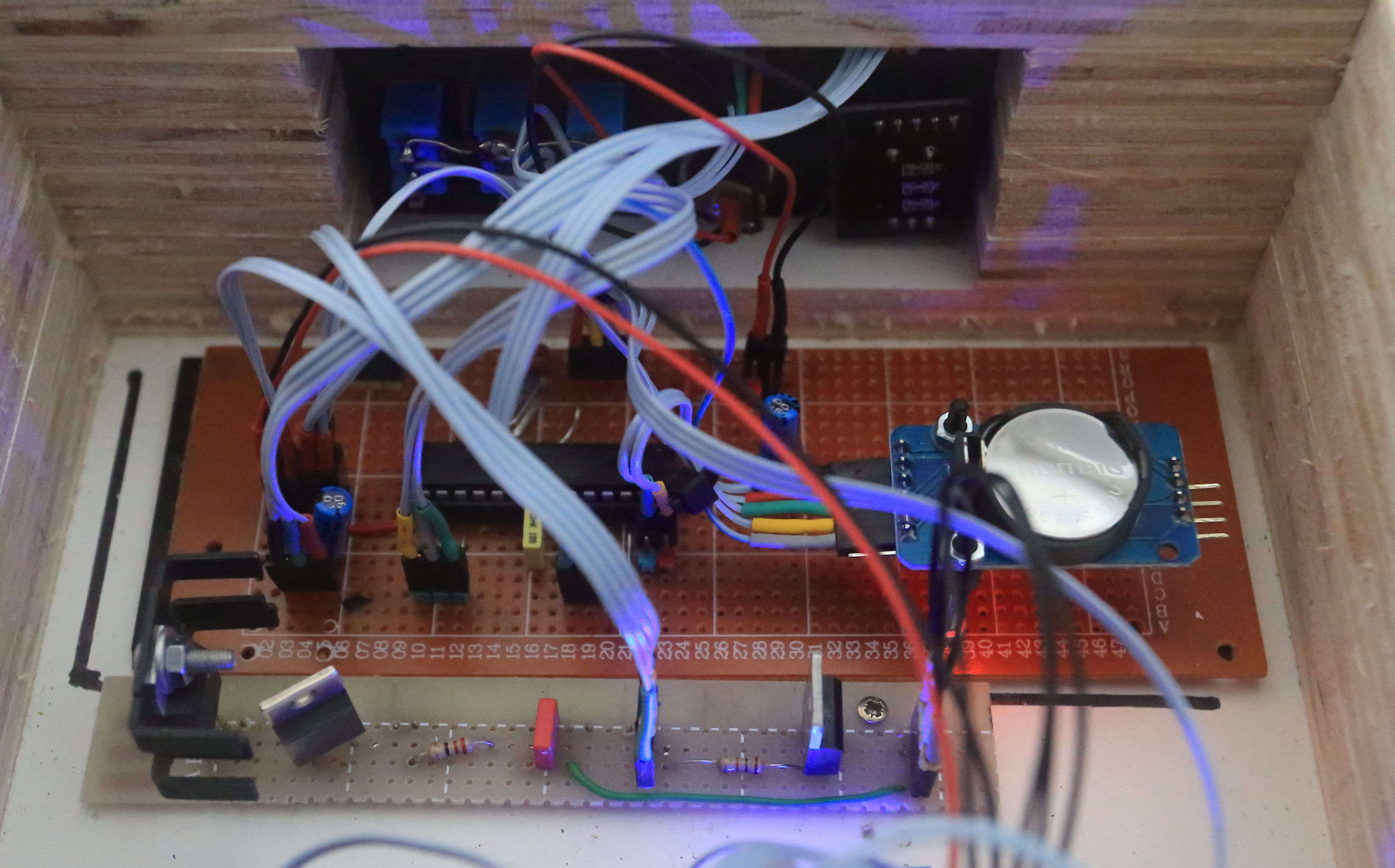
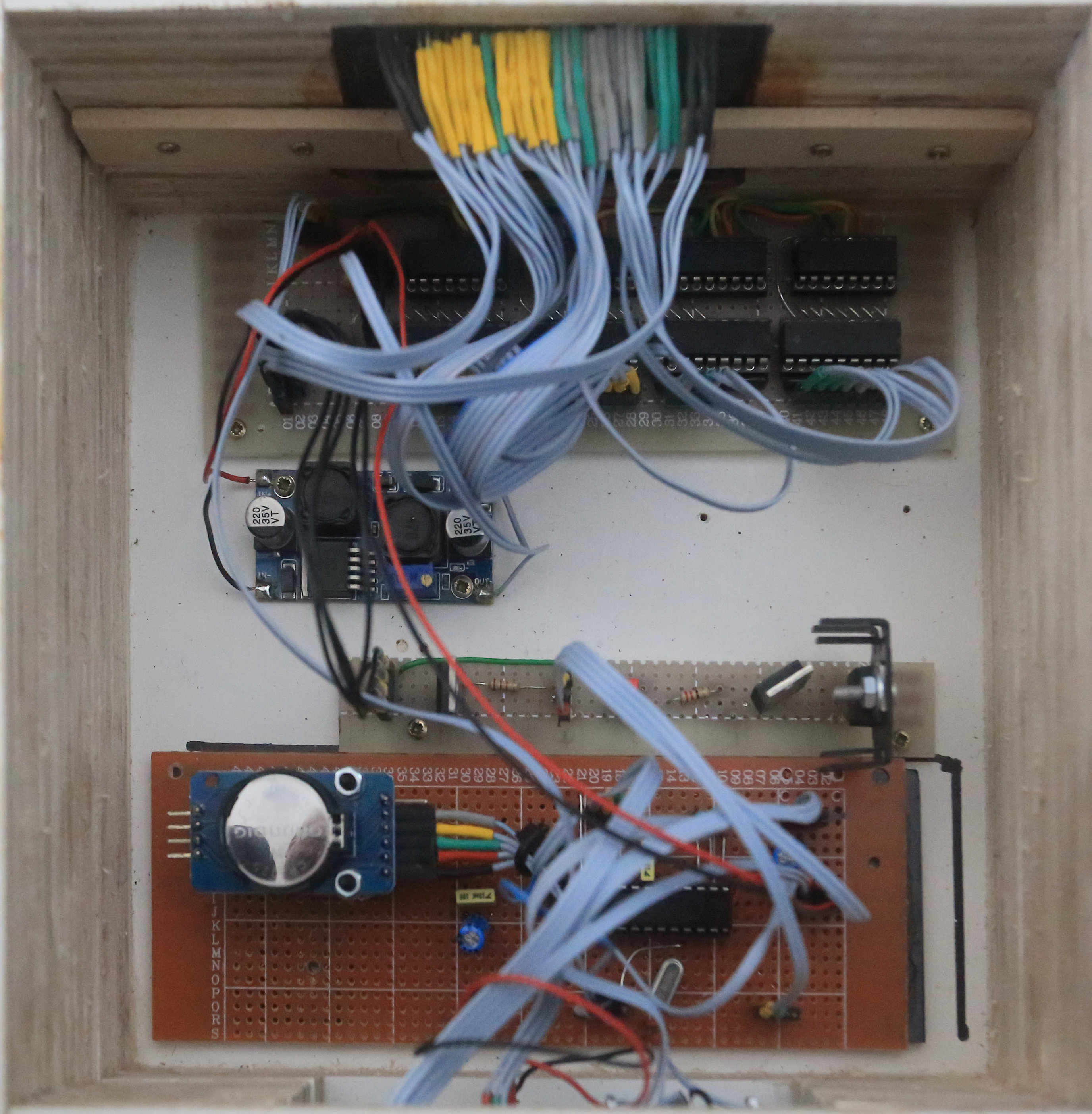
I am using 4 shiftregisters, 4 transistordrivers, a RTC ds3231 and a temperature sensor LM35.
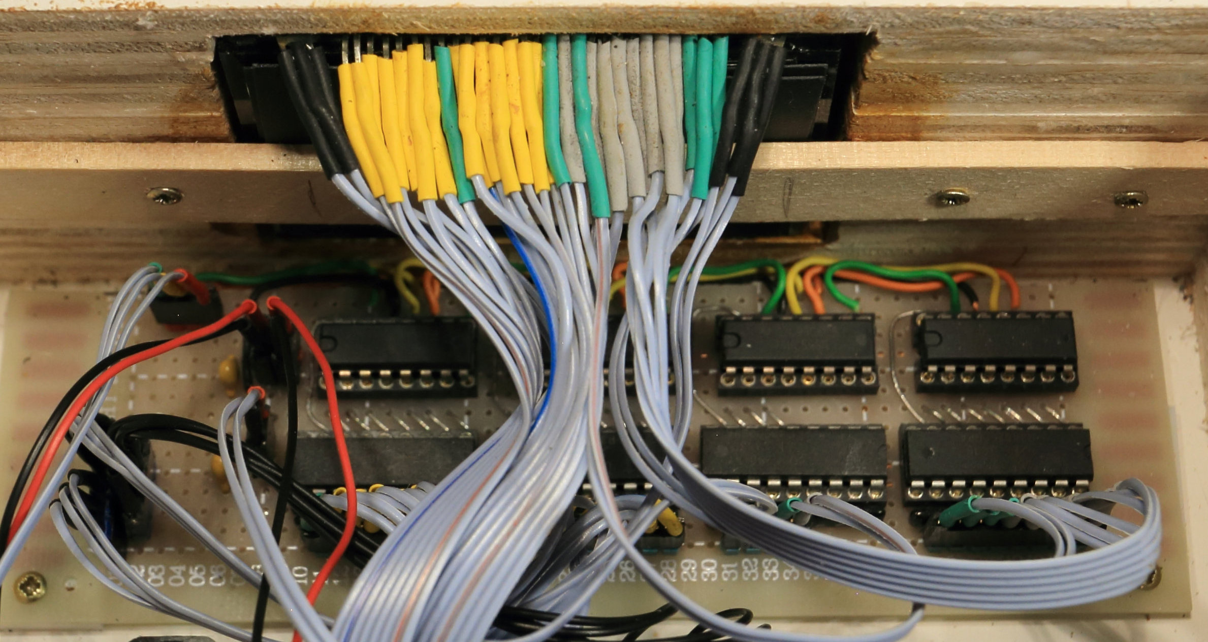

It took a lot of soldering to make the connections to the transistordrivers. See photo above. The black heat shrink tubing on the left and right are the filament connections.
When you look at the schematics, you see that the vfd48 displays has connection 5 that is not used, because this is not a true vfd48, but a vfd display lookalike. U8 buckconverter is the voltage for the grid and anode voltage. Adjust it to 20 VDC.
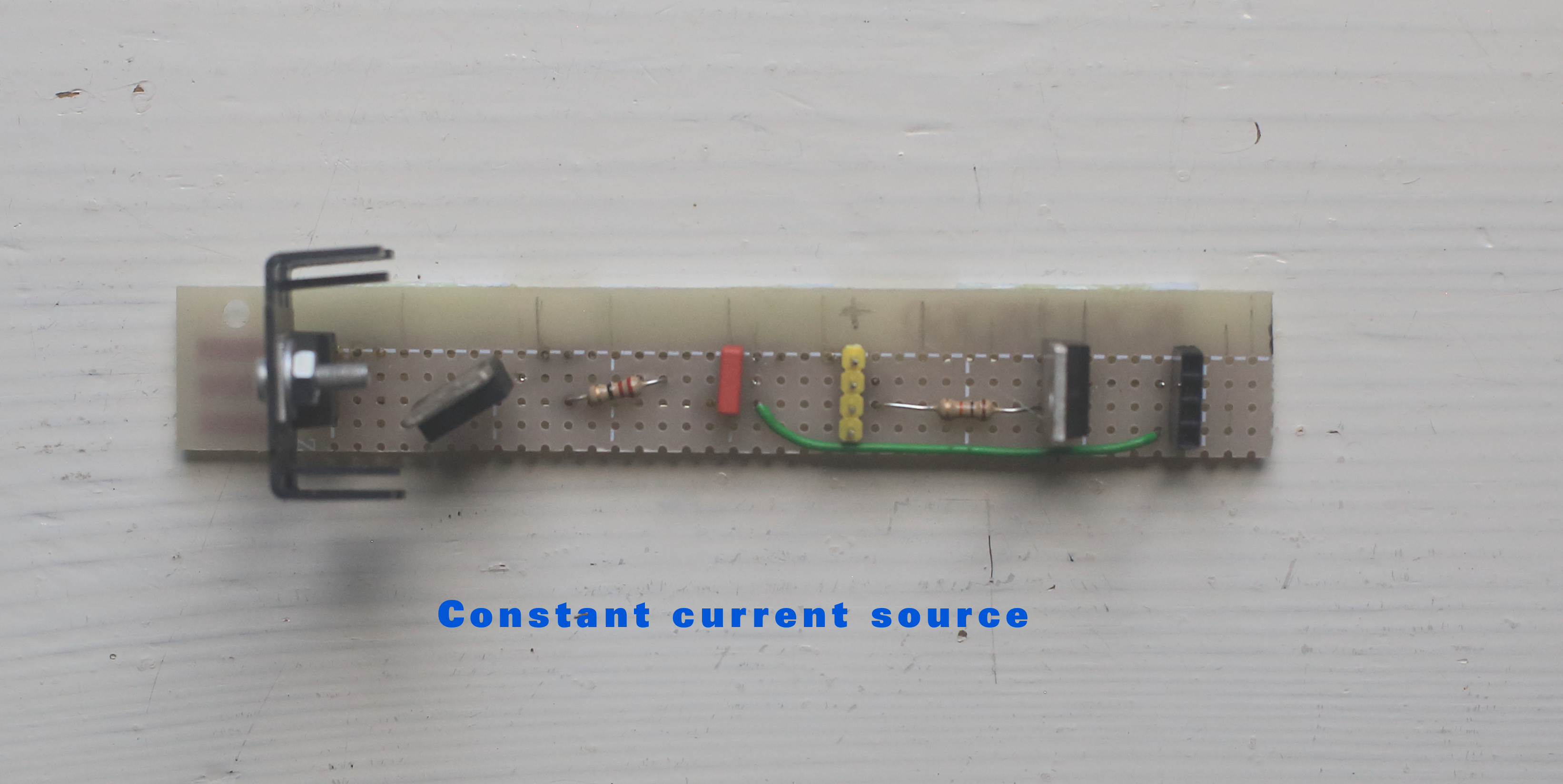
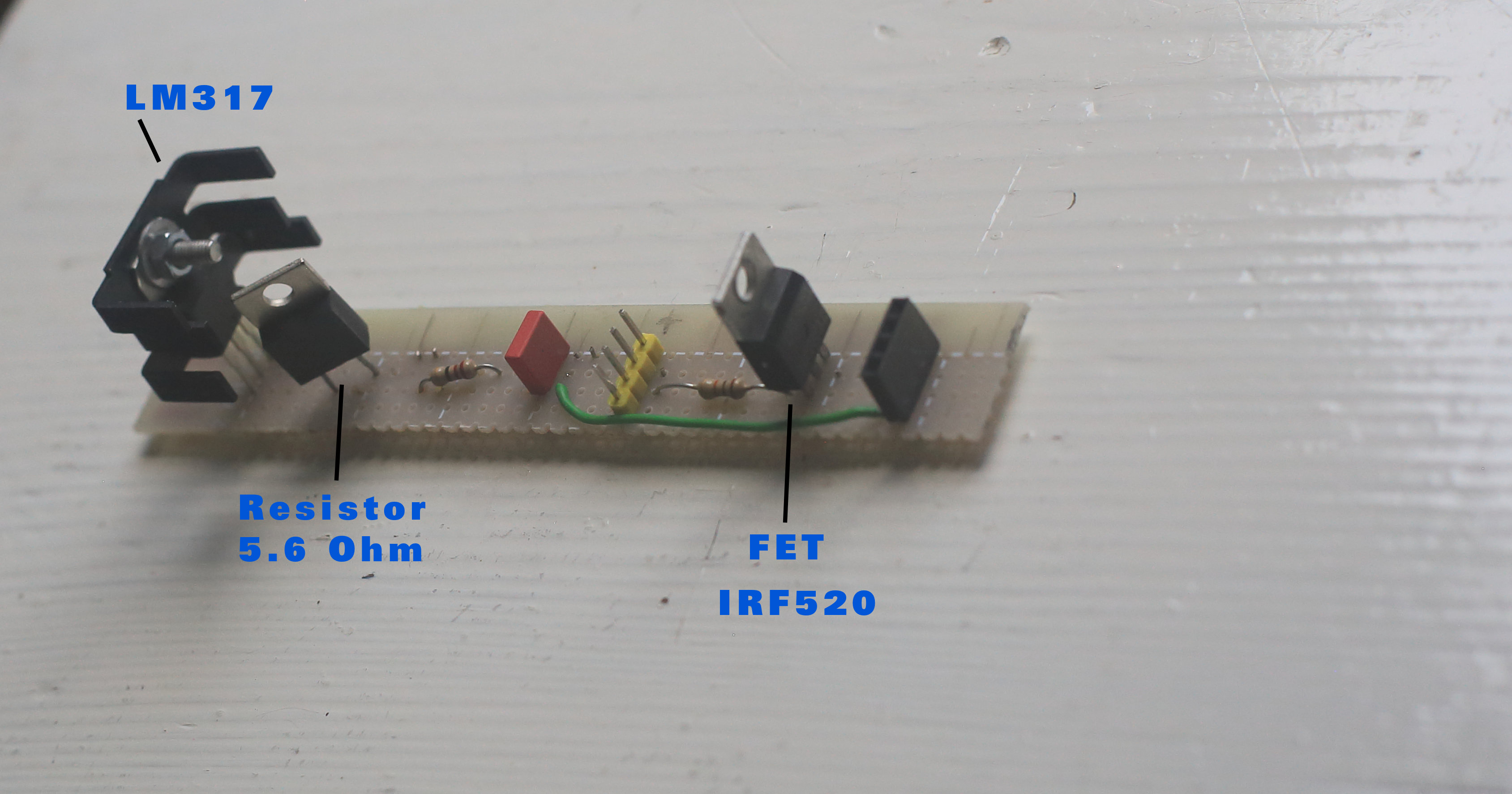
I made a constant current source (see photo above) with the LM317 to control the current for the filament. (Limit the inrushcurrent) With two resistors parallel (5.6 Ohm and 22 Ohm) the current is 1.25 /4.46 = 280 mA. The FET transistor (IRF520) is controlled by output D6. So the program can switch on or off the filament.
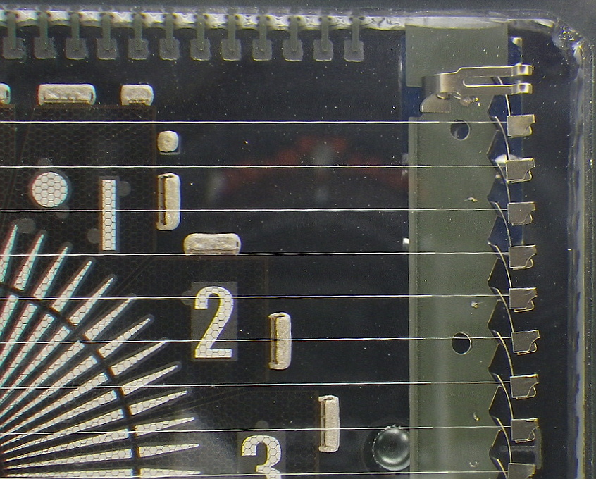
The output of shiftregister IC1 A0 connects to pin 6 of VFD48. This is the first green connection right (see photo). The numbering is from right to left, 6 to 33 (most right green = 6, most left yellow =33)
In the schematics output A0 of the shiftregister connects to input 8 of the transistordriver, output 8 connects to pin 6 of the vfd48, etc.
So: (see page 6 of the datasheet)
VFD48  -  IC1         VFD48  - IC2     VDF48  - IC3    VFD48  - IC4
Pin 6  -  A0          Pin 14 - A0      Pin 18 - A0     Pin 26 - A0
Pin 7  -  A1          Pin 15 - A1      Pin 19 - A1     Pin 27 - A1
Pin 8  -  A2          Pin 16 - A2      Pin 20 - A2     Pin 28 - A2
Pin 9  -  A3          Pin 17 - A3      Pin 21 - A3     Pin 29 - A3
Pin 10 -  A4                           Pin 22 - A4     Pin 30 - A4
pin 11 -  A5                           Pin 23 - A5     Pin 31 - A5
Pin 12 -  A6                           Pin 24 - A6     Pin 32 - A6
Pin 13 -  A7                           Pin 25 - A7     Pin 33 - A7
Technical Implementation: Multiplexing and High-Voltage Driving
This project reveals the hidden layers of simple vacuum-to-light interaction. The core of the operation is a multiplexing (or grid-scanning) strategy. The Arduino code interprets the time values from the RTC and rapidly cycles through the VFD's 12 grids, lighting the appropriate anode segments for each grid in sequence to create the illusion of a stable, fully lit display. This is coordinated by the shift registers and transistor drivers which handle the high-voltage switching required for the anodes and grids.
Program
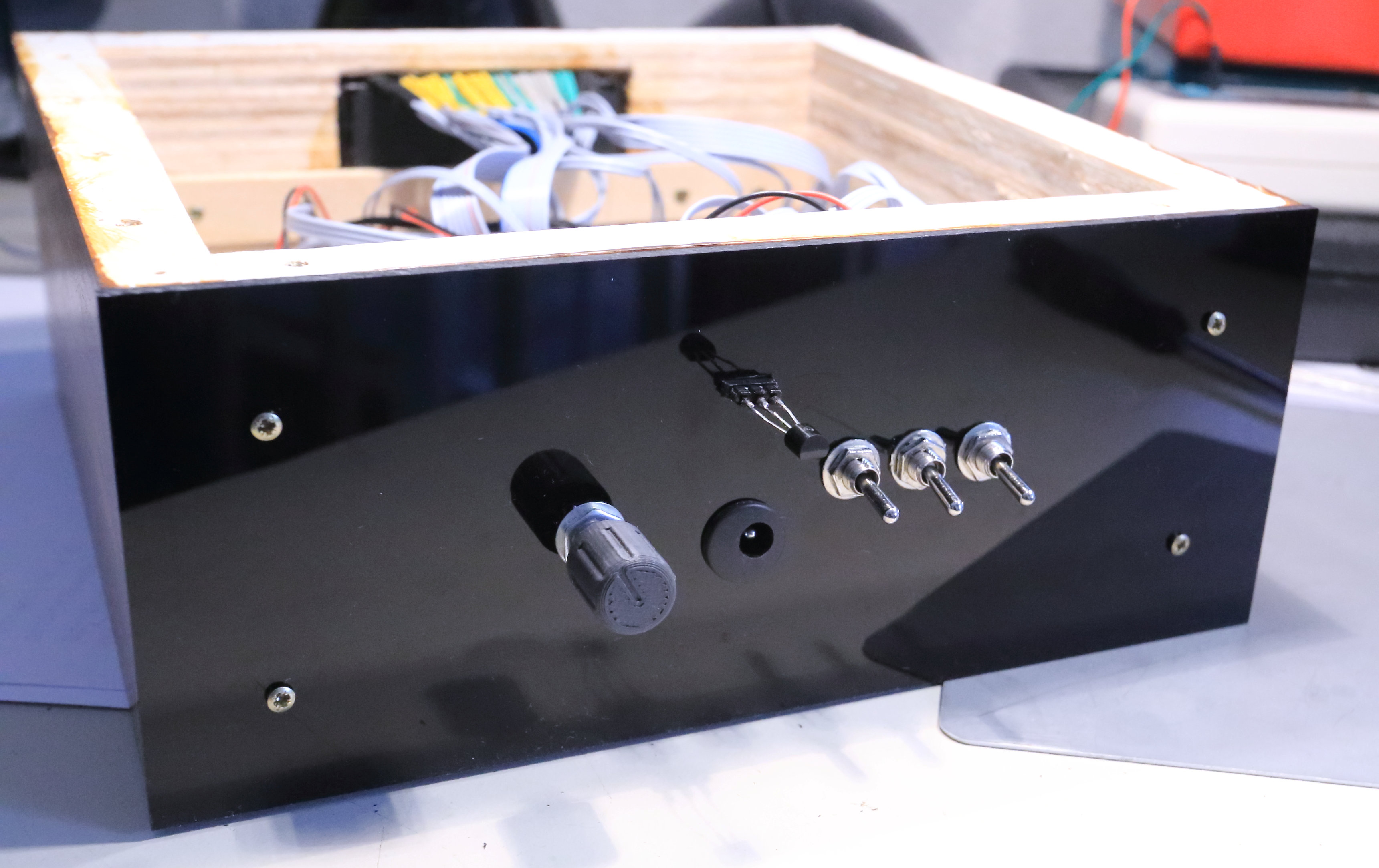
The program checks in the main loop the status of the three switches.
With three switches there are 8 functions.
The 8 functions are:
function 000: Display time with a small secondhand
function 001: Display time with a large secondhand
function 010: Display time without secondhand
function 011: Display temperature
function 100: Adjust hour
function 101: Adjust minute ( and seconds)
function 110: Stand By
function 111: Nightmode (between 0 - 8 am >> No display)
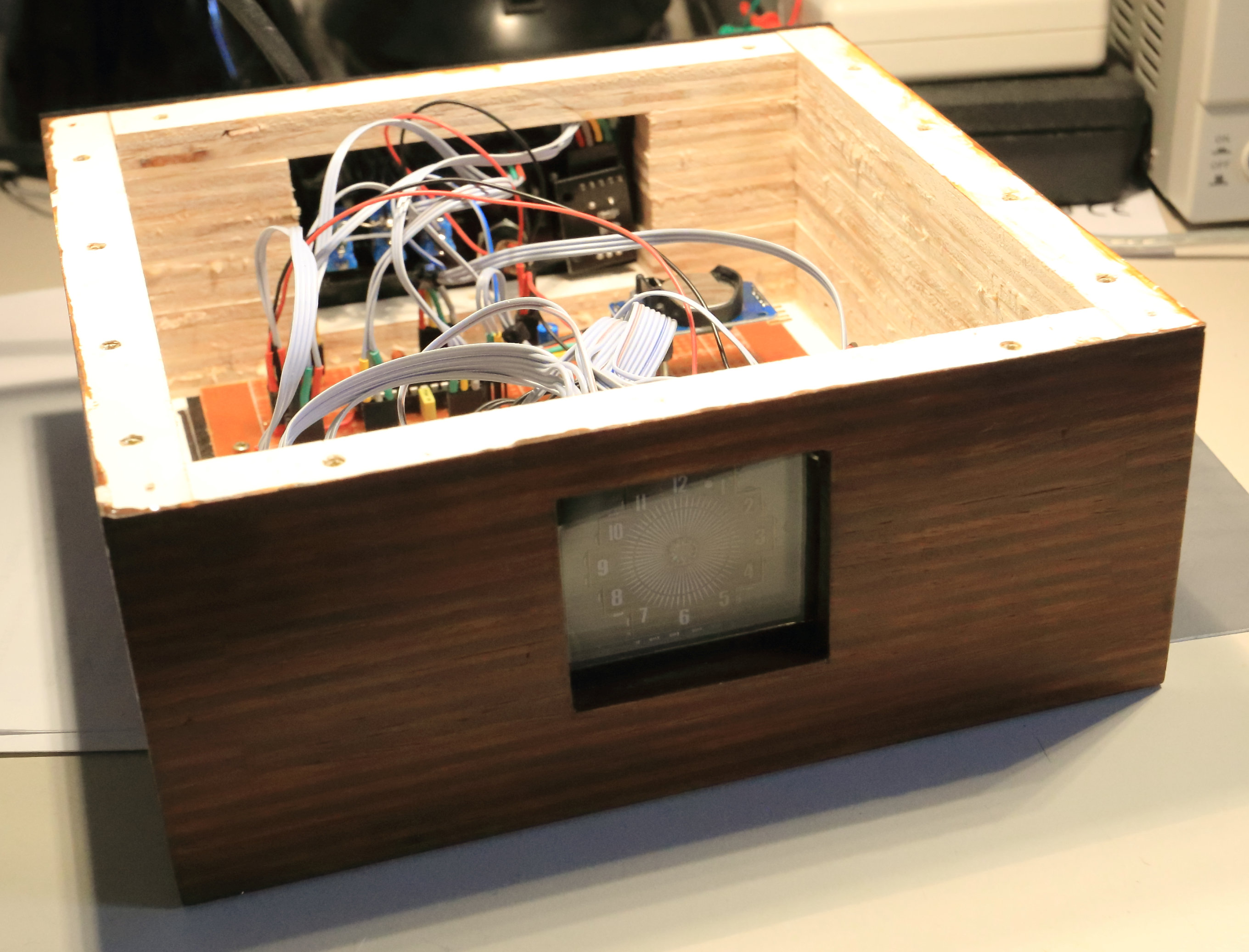
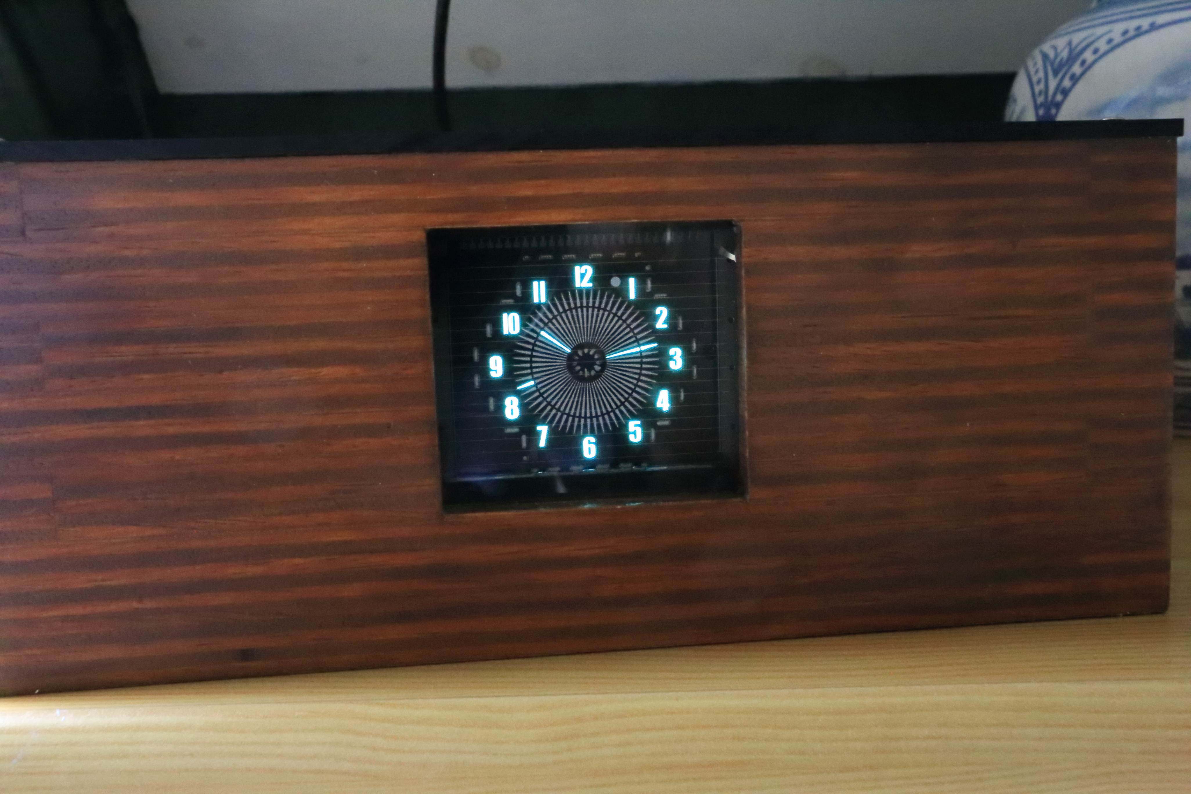
Function 011 shows the temperature: (See photo above)
The small indicators at the 12,2,4,6,8 and 10 positions are lit. The minutehand shows the temperature in celsius. As you can see at the photo the hand is at the 25 minutes position, indicating 25 degrees of celsius. Also a small hand between 12 and 2, indicating the number of tenths. The small hand indicates 5, so the temperature is 25.5 degrees celsius.
The power consumption of the clock is only 5x0.43=2.15 Watt. See photo below
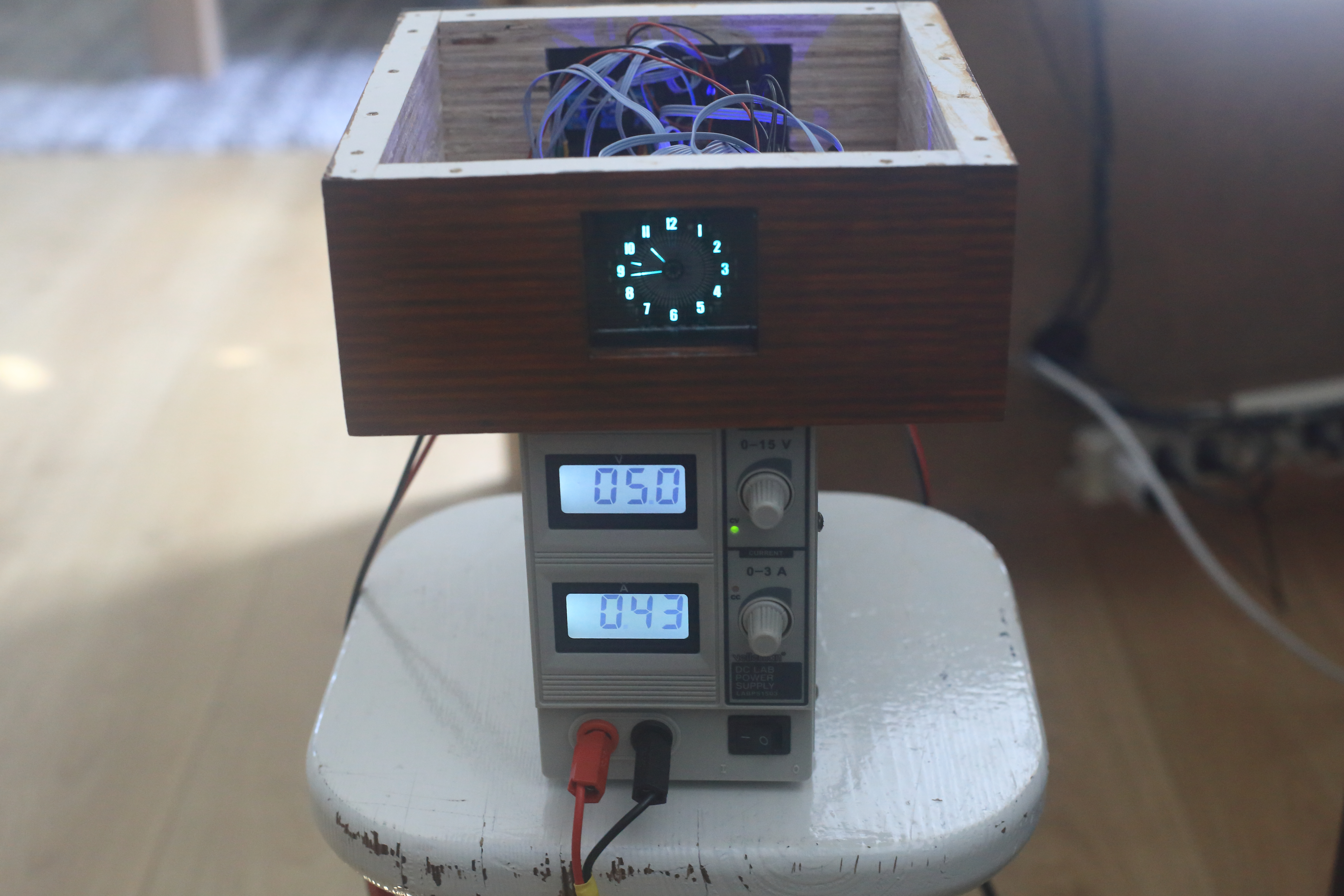
The effect of the constant current source can be watched in the video below. It is the function 110 - Stand By to normal mode. You can see that the current is only 80 mA when the filament is switched off and when switched on it will go to 0.43 A, (430 mA) and also the display is slowly getting its full brightness.
Hardware Infrastructure
- Arduino Nano: The "brain" of the project, managing timing sampling and coordinating the VFD multiplexing.
- VFD48-1202FN Display: Providing high-contrast vintage-style visualization.
- DS3231 RTC Module: Acts as the high-precision timekeeping heart with its temperature-compensated crystal.
- High-Voltage Boost Converter/Module: Provides the elevated voltage (adjusted to 20V DC in this build) required to drive the VFD's grids and anodes.
- Constant Current Source (LM317): Provides clear and stable power for the VFD cathode filament, limiting inrush current.
- Shift Registers & Transistor Drivers: Form the critical interface between the Arduino's logic-level signals and the high-voltage demands of the VFD.
Future Expansion
- OLED Dashboard Integration: Add a small OLED display to show metrics like "High Voltage (V)" or "Power Consumption (mA)."
- Multi-sensor Sync: Connect a PIR sensor to enable an "Auto-Off" feature when no one is in the room.
- Cloud Interface: Add WiFi/BT connectivity to log time history or adjust settings via a smartphone dashboard.
- Advanced Brightness Control: Implement PWM-based brightness adjustment that automatically changes based on ambient light levels.
[!CAUTION] This project involves High Voltage; always ensure all connections are properly insulated and secured inside an enclosure to avoid electric shocks!