Welcome to our exciting educational journey! Today, we’ll explore how to build a Digital Decoder Educational Kit using an Arduino Uno. This kit will help you understand how to convert binary inputs into decimal, octal, hexadecimal, and ASCII values. This project is designed to demystify the system of 1s and 0s that powers every computer on Earth. By building this trainer board, you will learn how to physically manipulate binary data and see it instantly transformed into the numbers and letters humans understand.
Computational Foundations & Binary Logic Overview
The Digital Decoder Kit is a masterpiece of Interactive Pedagogy. At its core, it teaches the concept of Positional Notation. By using eight physical DPDT switches, the user "toggles" each bit of a 1-byte (8-bit) number. This project demonstrates the bridge between "Hardware High/Low" states and "Software Logic," showing how electricity flowing through a simple switch can represent everything from the number 255 to the letter 'A'.
Hardware Infrastructure & The Instructor Tier
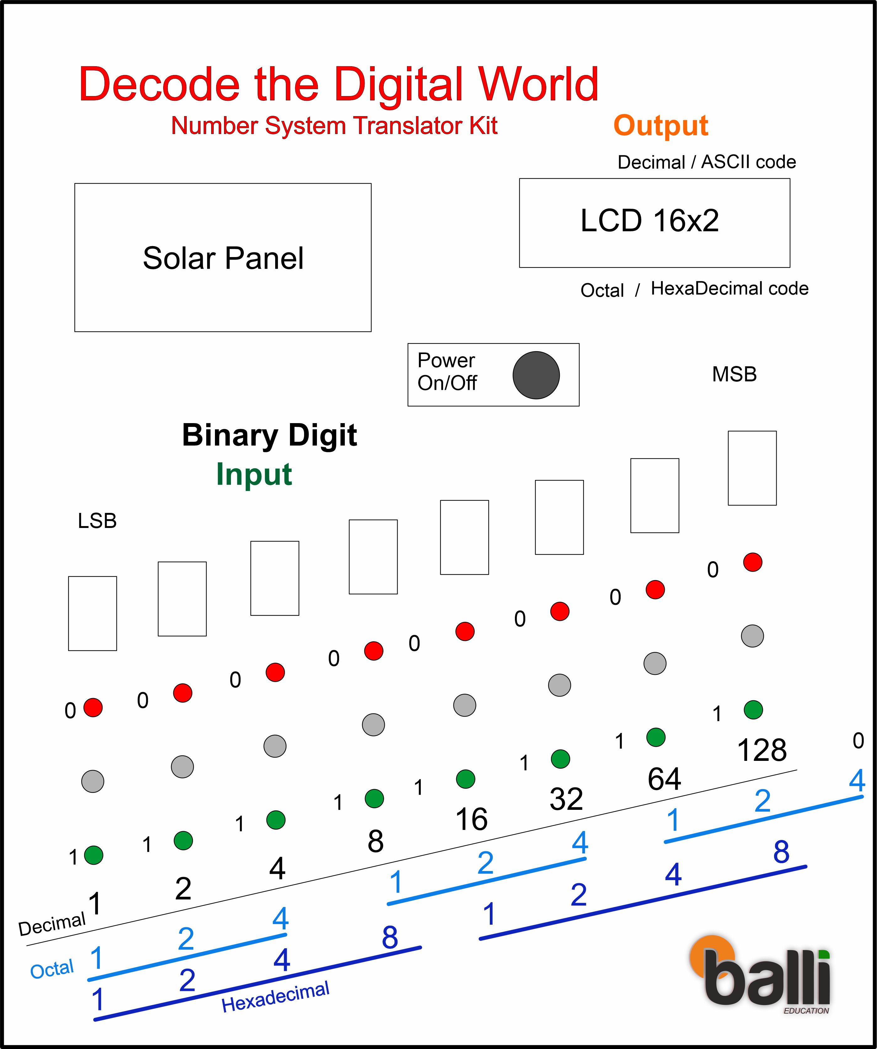
Design of Front Panel for Digital Decoder Trainer Board Kit:
- Arduino Uno Rev3: The brain of the system. It monitors eight digital pins, reconstructing the state of the physical switches into a single 8-bit integer.
- DPDT Input Modules: These switches act as the "Keyboard." Each switch is paired with a Red LED (0/Low) and a Green LED (1/High), providing immediate tactile and visual feedback of the "Bit State."
- 7-Segment Displays: Eight individual displays are used to show the digit '1' or '0' for each bit. This creates a massive, readable binary string on the trainer board’s face.
- 16x2 I2C LCD: The "Output Terminal." It takes the 8-bit binary value and displays its four primary interpretations: Decimal (base 10), Hexadecimal (base 16), Octal (base 8), and ASCII (character).
- Dual Power Logic: The kit is designed for fieldwork, featuring a solar panel and rechargeable battery module that ensures the board can run independently of a computer or wall outlet.
Input Method:
In our input method. We'll use DPDT switches to represent binary values. Each switch can be toggled to give a High (1) or Low (0) input. To visualize these inputs, we have red LEDs for Low and green LEDs for High, which will help us ensure that our inputs are correct and Seven Segment Display that shows input 1 for high and 0 for low voltage.
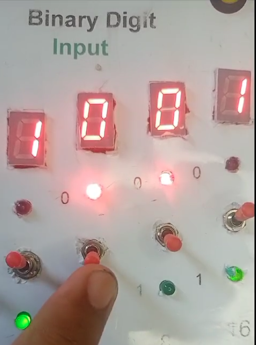
Here’s how our DPDT switches are wired: when the switch is toggled up, it connects to a green LED indicating a High input, and when toggled down, it connects to a red LED indicating a Low input. These states will be read by the Arduino to determine the binary value.
Next, we use a seven-segment display to show the binary digit of each input. This visual feedback is crucial for understanding how each switch position translates to binary values.
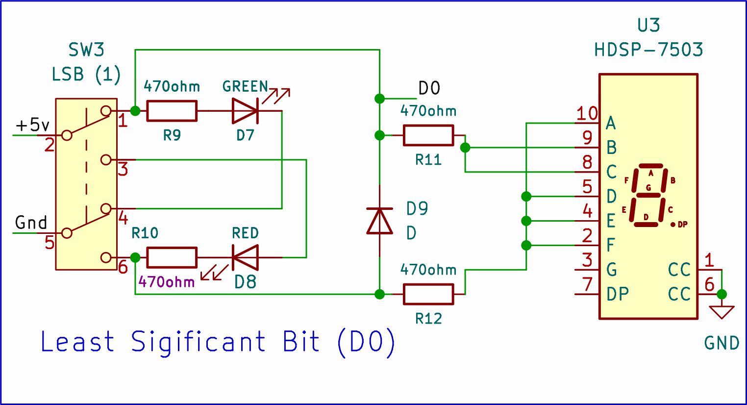
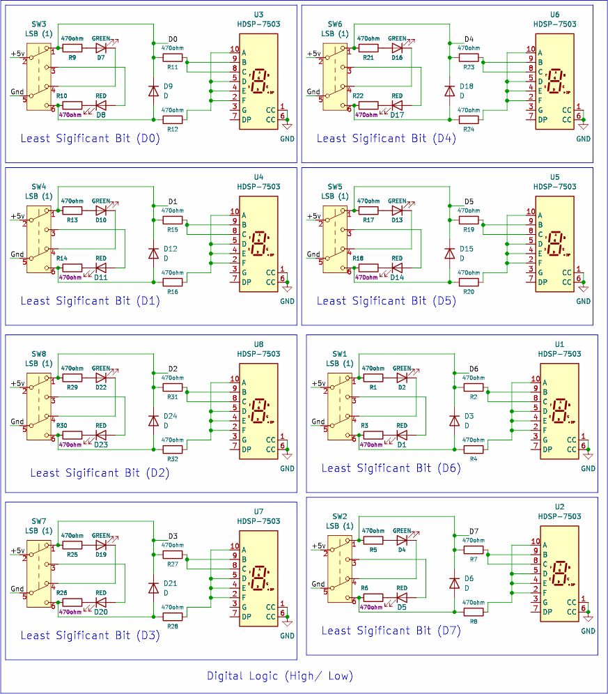
As you can see in the circuit diagram, a diode and two 470-ohm resistors are connected across the seven-segment display to show digits zero and one. The D0 label is the port for connecting as input to the Arduino Uno. This is a one-bit input circuit. Similarly, for an 8-bit input, we would need eight input modules.
Output Method:
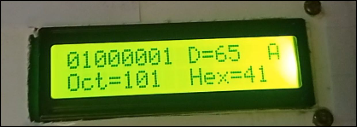
Our main output device is a 16x2 LCD screen. It will display the converted values: decimal, octal, hexadecimal, and ASCII characters, along with the 8 input bits.
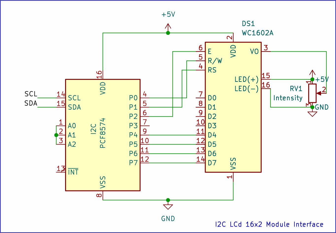
This circuit diagram shows an I2C LCD connected to an Arduino Uno. The I2C interface uses only two wires (SDA and SCL) for data transfer, simplifying connections compared to regular LCDs. These wires connect to specific I2C pins on the Arduino (often SDA to A4 and SCL to A5). Power lines (ground and positive voltage) are also connected to the LCD for proper operation. This I2C Multiplexing keeps the wiring clean, leaving the other pins free for the complex 8-bit input array.
BRAIN OF SYSTEM:
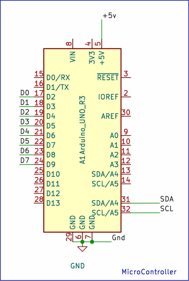
This circuit diagram showcases two key components connected to an Arduino Uno.
An 8-bit input module bridges ports D2 to D9. This module likely consists of DPDT switches that allow you to input binary data (0s and 1s) using eight separate pins on the Arduino.
Additionally, an I2C LCD module connects through just two wires, SDA and SCL. These designated I2C pins on the Arduino communicate with the LCD, allowing it to display information. Separate power lines (ground and voltage) are also connected to the LCD to power its operation.
Technological Logic and Bitwise Reconstruction
The software performs a series of mathematical "Rotations" and "Coercions" every second:
- The Bit-Scan: The Arduino reads pins D2 through D9. It uses a loop to check each pin; if a pin is
HIGH, it "Sets" the corresponding bit in a 1-byte variable using the formulavalue |= (1 << i). - The Base Conversion Engine: Once the 8-bit number is formed, the Arduino doesn't need complex math—C++ has built-in handlers for printing in different bases (
DEC,HEX,OCT). - ASCII Mapping: The system treats the 8-bit number as a character index. For example, if the switches represent
01000001(binary 65), the LCD will display the character 'A'.
Two ways to power your Arduino project !
Solar Power: Connect a solar panel to rechargeable cells through a rechargeable module. The voltage regulator (protects components) outputs a steady 5v which can power your Arduino and other components directly.
Direct Power: Use a USB cable and connect your Arduino to a computer or a USB power bank. This provides immediate power for testing and use.
Why This Project is Important
Mastering binary decoding is the "Level 1" requirement for any computer scientist or mechatronics engineer. It teaches you how data is physically stored in Memory and Registers. Building this as a physical "Trainer Board" provides a much deeper understanding than simply typing code. It makes the abstract world of computer logic tangible, turning an invisible electrical state into a visible, understandable piece of information.