In the world of modern security systems, the integration of software and hardware is a crucial skill. This DIY Digital Lock project is an excellent learning prototype for beginners in Embedded Systems, utilizing basic components found in common Arduino learning kits to create a computer-controlled locking system.
The highlight of this project is the collaboration between Arduino (which acts as the hardware controller) and Processing (which serves as the interface on the computer screen). The system uses an LCD to display status, and a DC Motor as the actuator for the locking mechanism, with an H-bridge circuit as the core for controlling direction and power delivery.
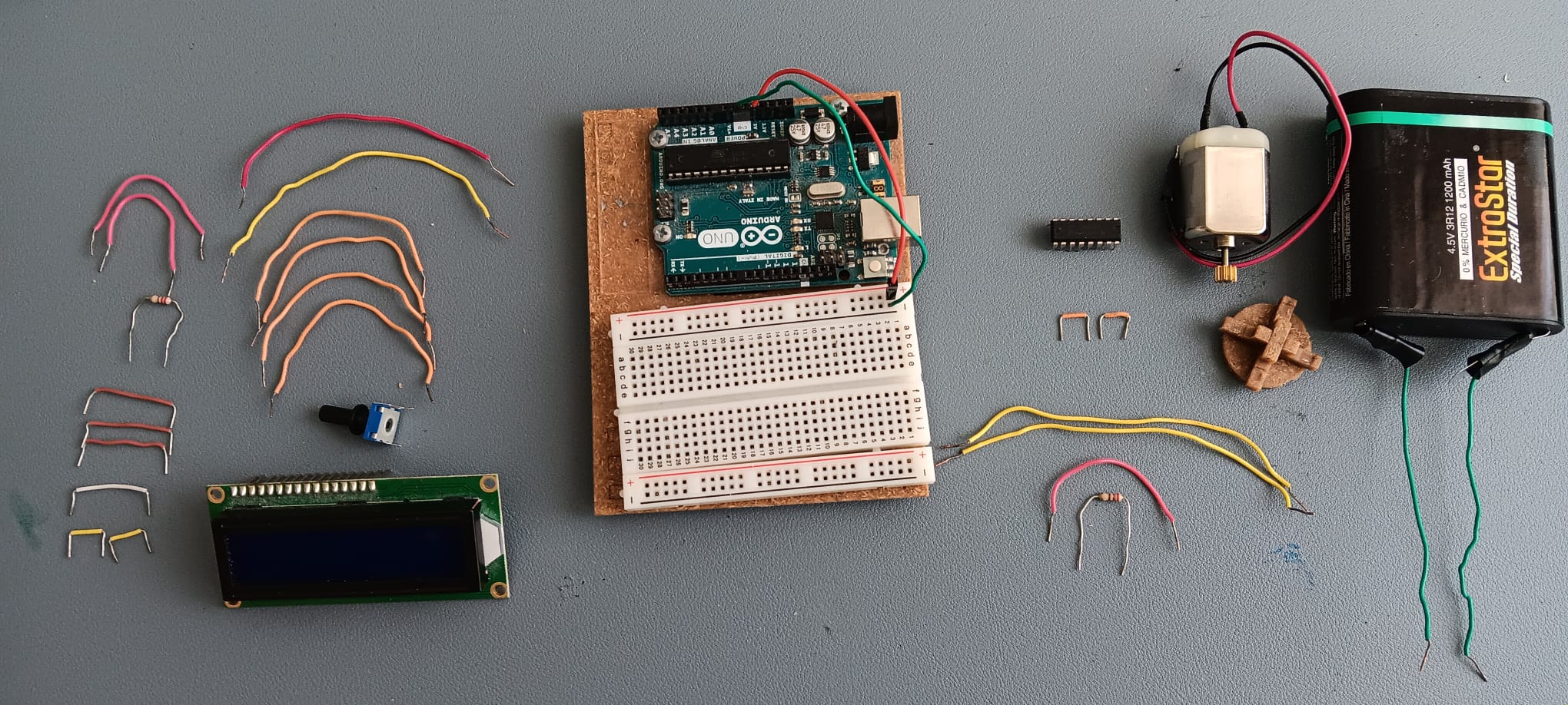
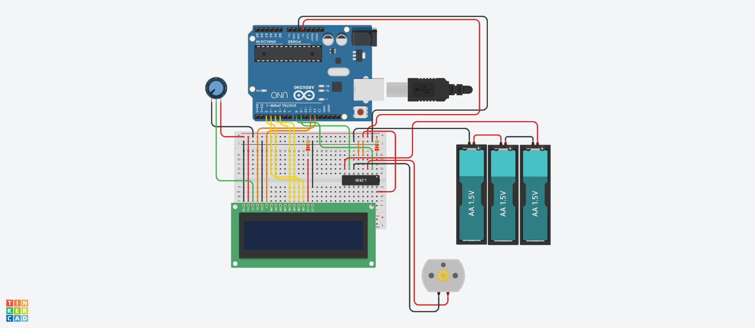
Step 1: Hardware Components
The selection of components for this project emphasizes cost-effectiveness and understanding of basic electronics:
- Arduino Board: (Uno or similar model) Serves as the main microcontroller.
- Jumper Wires: For wiring the circuit.
- LCD 16x2 (Standard): A parallel display (without an I2C module) to learn 4-bit mode data transmission.
- Potentiometer 10 K ohm: For adjusting the contrast of the LCD screen.
- DC Motor (Type 130): A small 1-5 Volt motor for simulating the lock bolt action.
- Resistors 220 ohm (2 pieces): For current limiting (e.g., for the LCD backlight).
- Battery 4.5 Volts: External power supply for the motor to prevent current surges into the Arduino board.
- H-bridge L293DNE: A very important motor control IC, allowing us to command the motor to reverse direction (lock/unlock) and provide voltage isolation between the logic and power circuits.
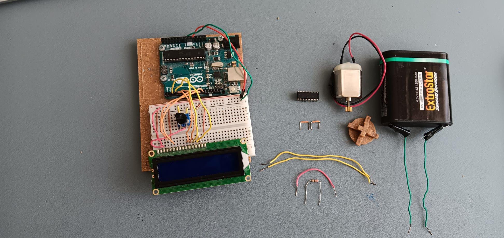
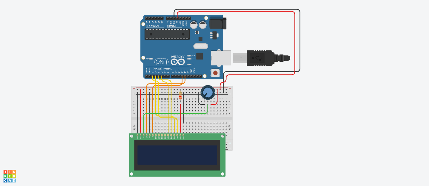
Step 2: Connecting the LCD 16x2
Since we are not using an I2C module, the connection requires multiple signal wires for parallel data communication, consisting of the Register Select (RS), Enable (E) pins, and data pins D4-D7.
Operating Principle:
Arduino will send character data via the LiquidCrystal.h Library. We need to connect a Potentiometer to the V0 pin of the LCD to adjust the voltage controlling character intensity. If connected correctly, you will see operational status like "Opening" or "Closing" appear on the screen while the system is running.
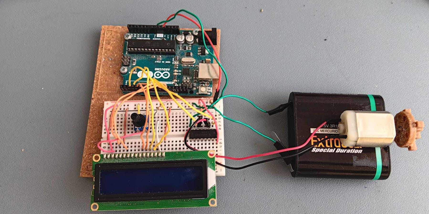
Step 3: Motor Drive System with H-Bridge
The core of locking and unlocking is controlling the DC motor to rotate clockwise and counter-clockwise. We use the L293DNE IC, which is a Dual H-Bridge Motor Driver.
Why use an H-Bridge and a separate battery?
- Direction Control: A typical DC motor connected directly to power will only spin in one direction. The L293D allows us to reverse the polarity via software.
- Power Isolation: Motors generate electromagnetic interference (EMF) and draw high current. Using a separate 4.5V battery (3 x 1.5V cells) helps the Arduino operate stably and prevents it from restarting when the motor starts.
Step 4: Software Integration
This project relies on Serial Communication between the computer and Arduino:
Processing IDE: Creates a GUI (Graphic User Interface) on the computer screen. When the user clicks the "Lock" or "Unlock" button, the program sends a character code (e.g., 'L' or 'U') via USB to the Arduino board.
- Download Processing: https://processing.org/download
Arduino IDE: Receives values from the Serial Monitor. If a predefined character is received, it will command the Digital Pins connected to the L293D to operate (e.g., one pin HIGH and the other LOW) to rotate the motor, along with updating messages on the LCD screen.
- Download Arduino IDE: https://www.arduino.cc/en/software/#ide
Code Logic:
- Unlocked State: The motor rotates in direction A for 1-2 seconds and then stops. The LCD displays "Unlocked."
- Locked State: The motor rotates in direction B for 1-2 seconds and then stops. The LCD displays "Locked."
By combining both hardware and software, you will have a digital lock system that can be effectively applied to real mechanisms, such as small door latches or smart storage cabinets!