Premise:
I'm pretty new to Arduino and electronics in general. Browsing around I soon noticed these orange glowing tube projects that a lot of people made. Came to find out that they are called nixie tubes and are vintage electronics used in the 60s and 70s for displaying numbers and symbols. Plus, they are not made anymore (with one exception) and those tubes that people used are from old stocks or gutted from old equipment. Can this get any cooler I thought? Then I learned that to light up they need about 180 Volts... That scared me enough to put my plans on the self until I had a little more experience with electronics.
Two projects later (a three wheel robot and a 1280 LED scrolling text display) I felt ready to get my hands on those dusty old tubes and treat myself and my living room to a great looking nixie clock.
So, here we are.
Features:
The clock has the following features implemented:
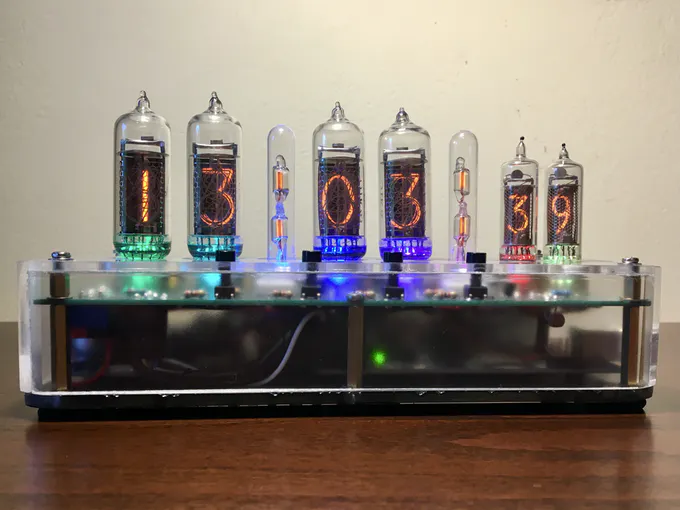
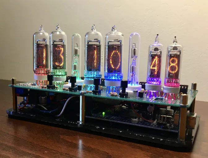
- Time display of course (only in 24 hour format since I prefer that), with blinking colons
- Accurate time keeping and battery to keep the time when the power is off
- RGB LED backlight on the digits and the semicolons, with eight different color effects
- Light sensor and automatic dimming of the LEDs depending on the light in the room
- Test mode which circles through every digit and LED color plus display of the light sensor reading
- Four buttons which can control the following:
- - set the time
- - circle through the LED color effects
- - turn the LEDs on and off
- - enter and control test mode
- Anti-Cathode-Poison (ACP) routines to keep the tubes in healthy condition
- Routine that turns the tubes and LEDs off at night when there is no light in the room to save power and increase their lifetime
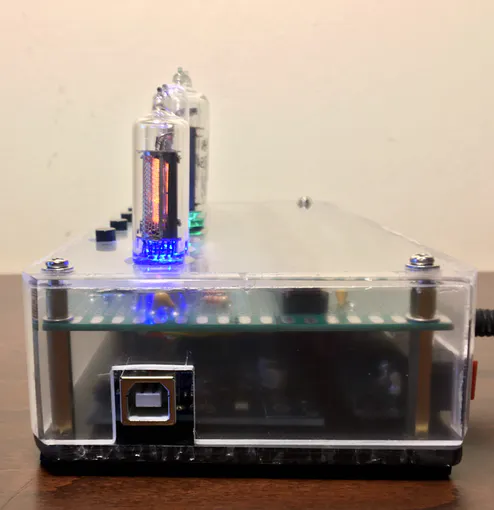
- easy access for repairs
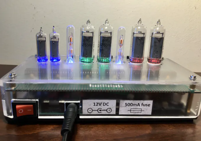
- On-off power switch
- Fuse for safety
Design:
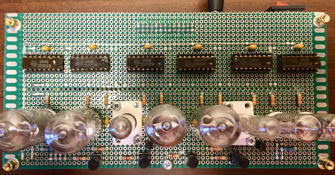
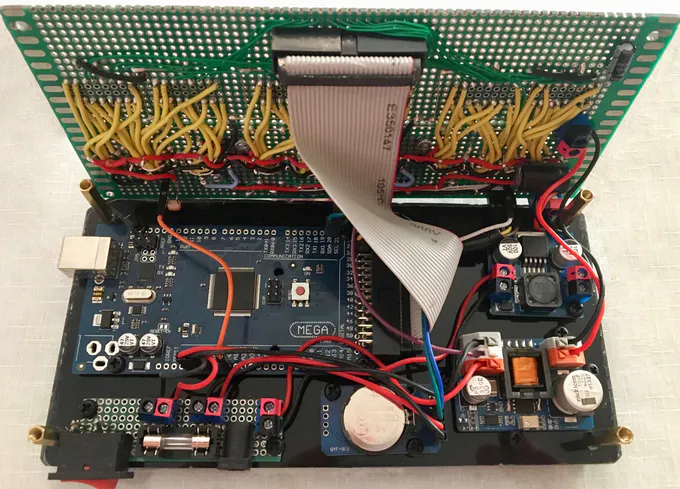
So, the thinking behind the design was to make it as simple as possible so all the components could be placed on one perfboard neatly. The perfboard had to look presentable since the cover was going to be see-through. I did not use multiplexing because to do so I would have to include extra circuitry to make each nixie turn on and off individually and since those soviet nixie chips (K155ID1) are cheap enough, it was easier to use six of them. I also had a lot of space on the bottom floor for an Arduino mega, so the many pins needed for each chip (4 per chip) would not be a problem. The IDC ribbon cable helped a lot making all those pins easy to connect. Again, simplicity was the goal and this was the simplest way considering my skills and understanding.
EXPANDED TECHNICAL DETAILS
Generating and Switching 170V DC
An Arduino is a 5V logic system. A Nixie tube requires approximately 170V DC to strike the neon plasma.
- The Boost Converter: This project uses a specialized High Voltage DC-DC Step-Up Converter (the NCH6300HV) to turn the 12V input into the required ~174V.
- The K155ID1 Driver IC: The Arduino cannot output or switch 170V directly. The solution is the K155ID1 chip (or its SN74141 equivalent). This is a BCD-to-Decimal decoder chip engineered in the 70s to natively handle high voltages.
- How it Works: The Arduino sends a tiny 4-bit 5V binary signal (e.g.,
0100for the number 4) to the driver. The K155ID1 chip decodes this signal and sinks the 170V path from the Nixie tube's corresponding cathode (e.g., "Wire 4") to Ground, illuminating that digit.
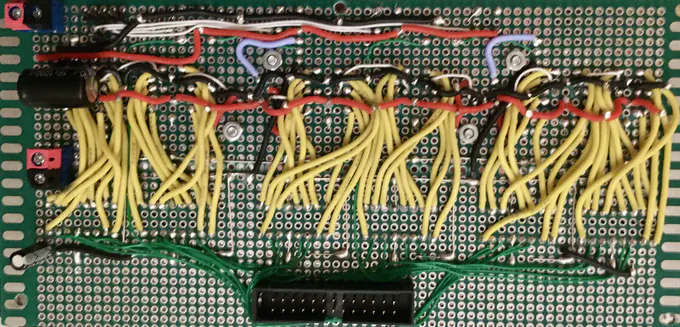
Engineering the Custom Perfboard
This project teaches advanced layout and high-voltage safety.
- You cannot use a breadboard, as 170V can arc across the internal clips and melt them.
- You must carefully solder the maze of driver ICs, tube sockets, and supporting components onto a Perforated Fiberglass Board, meticulously managing thick high-voltage traces and thin 5V logic traces to prevent catastrophic shorts or arcing. The images above show the clean, organized result of this careful planning.
For the backlighting I used the WS2811 addressable RGB LEDs which do not need much extra circuitry and can be easily controlled individually to create some cool effects.
The clock gets its power from a simple 12Volt wall power supply I had laying around. For powering the tubes I chose a high voltage nixie power supply (12V to 174V) and a step down - buck - converter (12V to 5V) for powering the LEDs. The Arduino Mega is powered straight from the 12Volts of the wall power supply. Current consumption of the finished clock is at about 250mA.
Finnaly, for the time keeping part I choose a cheap ebay RTC module based on the DS3231 chip. It communicates with the arduino using the I2C protocol and is powered straight from the arduino 5V pin.
Lessons learned:
Since finding out how a nixie tube works, how to light it up and that kind of stuff is pretty easy online thanks to the articles that many folks have written on the topic, I decided that it would be more useful to talk about the things I learned making the project which I wish somebody had told me before starting. So, here we go:
- There are many nixie tube power supplies available on e-bay from chinese sellers that are pretty cheap. I bought some of them and they all worked, but not on the advertised capacities. What I came to find out is that this power supplies are copies of designs available online and are advertised as having the same capabilities with the originals. The problem is that since they use cheaper components than the originals, they can't really perform as advertised. In my case, the knock-off power supplies could not output enough current for all the six nixies and the colon lamps, so the nixies would fade when the colon were on and some numbers (number 2 mostly) would not light up fully. With another design, the flicker would go away but the power supply would get extremely hot. So, I ended up getting an original power supply that worked great and as advertised.
- You can get wires that are rapped in silicon rubber which, unlike PVC, does not melt with a soldering iron. This is really, really helpful when you are trying to solder many wires on a perfboard.
- Before connecting your nixie tubes, clean their pins with steel wool or something like that. Since they were made decades before, the metal pins can get oxidized. Cleaning them will save you from a lot of headaches and connection issues.
- Plugging and unplugging the tubes is hard because their pins bend easily. Especially on the IN-16 (small ones for displaying the seconds). If I did it all over again, I would prefer to use some tube sockets, connect the tubes on them and then (the sockets) on the clock pins - something like an in-between. This way I could plug and unplug the the sockets as many times as I wanted, easily and without risking damage on the tube pins. On ebay you can buy sockets like these. Or you can create your own ether on perfboard or PCB.
- Plan your algorithm before you start writing code. Making things as you go along works with small projects but as soon as things get a little more complex, spaghetti code is waiting around the corner. What I mean is that you need to plan the flow of information (variable values etc.) between the various parts (e.g. functions) of the algorithm, otherwise - when things get more complex - you end up with making one change and having five things broken! For example, you will often hear that using global variables is bad practice. Well, as soon as you get tangled into the spaghetti code, you'll understand why. Having a general plan of how information will flow helps a lot.
Bill of materials:
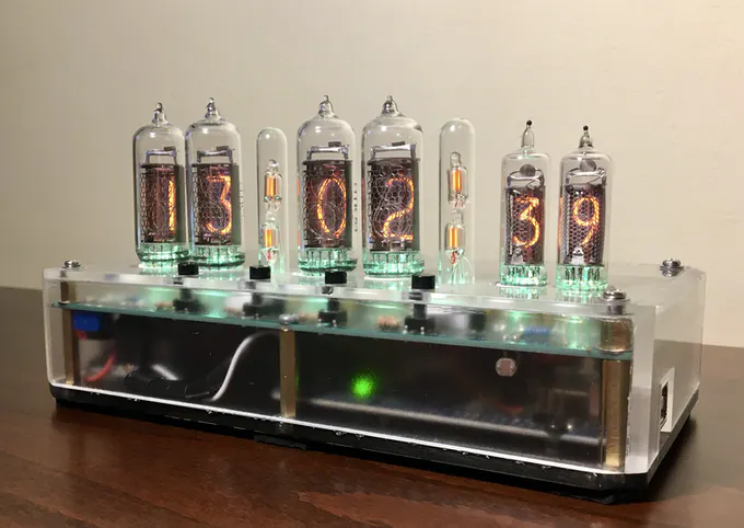
- 4pcs IN-14 Nixie tubes
- 2pcs IN-16 Nixie tubes
- 2pcs Glass Columns with 2 NE-2H Neon Lamps + Holders
- Prototyping perfboard 120x180mm double-sided
- Arduino Mega 2560 R3 without headers
- DS3231 AT24C32 I2C Precision RTC Module
- 6pcs K155ID1 nixie Driver ICs
- 2pcs MPSA42 A42 0.5A/300V NPN TO-92 DIP transistors
- 8pcs WS2811 RGB LEDs 5mm through hole
- Photo Resistor LDR 5mm
- NCH6300HV DC-DC power supply - Original from omnixie
- 3A mini DC-DC Step-down converter 5V fixed-output
- 20 resistors 1/4 Watt 5%, various values
- 14pcs ceramic capacitors 100nF
- Electrolytic capacitor 100µF 16V
- Electrolytic capacitor 1000µF 16V
- 7pcs 5.08mm 2Pin terminals
- IDC Connector 2x13 Pins male
- IDC Connector 2x13 Pins male angled
- IDC Ribbon Cable 2x13 Pins
- 6pcs DIP Sockets - 16Pins
- 4pcs mini push button switches
- Fuse holder THT mount 5x20mm
- Glass fuse 5x20mm 500mA
- Rocker Switch ON-OFF Red
- 5.5x2.1mm DC power plug jack square connector
- 56cm2 plexiglass, 4mm thickness