In this project, we make a cool speedometer for bikes or any automotive by using Arduino to broadcast the speed using Bluetooth to an Android application that we created using processing. The complete project is powered by an 18650 Lithium cell and hence highly portable along with your vehicle. To spice it up a bit more I have added the option of charging your mobile phone as it displays your speed. Yes, you can also use this as a power bank for your mobiles on the go as the 18650 has high charge density and can easily be charged and discharged.
I will completely guide you from scratch till the completion - the speedometer can be hooked up to your vehicle and tested. The cool feature here is that you can customize your Android app for your personalisation and add more features according to your creativity. But, if you do not want to build the app by yourself and just build the Arduino part, then no worries - just download the APK file (read further) and install it onto your Android mobile phone. Also, check the full video at the end.
So let’s see what materials we would need to build this project and plan our budget. All these components are easily available; if you have trouble buying any of these, let me know in the comment section.
Hardware Requirements:
- Arduino Pro Mini (5V 16MHz)
- FTDI board (for programming mini you can also use UNO)
- 3V to 5V DC-DC Boost converter with USB output charger
- TP4056 Lithium battery module
- Bluetooth module (HC-05/HC-06)
- Hall effect sensor (US1881/04E)
- 18650 Lithium cell
- Small piece of magnets
- Perf board
- Berg sticks connectors (male and female)
- Soldering Kit
- Small enclosure boxes to mount the kit.
Programming Requirements:
- Arduino IDE
- Processing IDE with android ADK (Only if you want to code your own app.)
- Windows/Mac PC
- Android Mobile Phone.
It might look like a handful of components and materials, but trust me once you complete this project, you will feel they are worth the time and the effort.
Measuring Speed using Hall Sensor and Arduino:
Before we get our hands on the hardware, let us know how we are actually going to measure the speed using Arduino. There is lots of way to measure the speed of a vehicle using Arduino, but using a hall sensor is the most economic and easiest way of doing it. A Hall Sensor is a component that detects the polarity of a magnet. For example, whenever one particular pole of the magnet is brought near the sensor, the sensor will change its state. There are many types of hall sensors available; you can use any one of those in this project but make sure that it is a digital hall sensor.
To measure the speed, we have to stick a small piece of magnet onto the wheel of the vehicle. Each time the magnet crosses the hall sensor, it will detect it and send the information to the Arduino.
An interrupt will be received by the Arduino each time the magnet is detected. We run a continuous timer by using
millis()
Function and calculate the time taken for the wheel to complete two rotations (to minimise error) by using the below formula:
Timetaken = millis() – pevtime;
Once we know the time taken, we can calculate the rpm by using the below formula:
rpm = (1000/timetaken) * 60;
Where (1000/timetaken) gives the rps (Revolutions per second) and it is multiplied by 60 to convert rps to rpm (Revolutions per minute).
After calculating the rpm, we can calculate the velocity of the vehicle using the below formula provided (we know the radius of the wheel).
v= radius_of_wheel * rpm * 0.37699;
The Arduino, after calculating the velocity, will broadcast it using the Bluetooth module. The complete code has been given below in the Code section. Also, check our other projects involving Bluetooth Module HC-05 here.
EXPANDED TECHNICAL DETAILS: Calculating Tangential Velocity (The Interrupt Math)
This project rips the rotational telemetry out of the physical world! The Arduino calculates exactly how fast the wheel is spinning using a Hall Effect sensor, runs the circumference geometry to deduce Kilometers Per Hour (km/h), and then transmits that data over a Bluetooth Serial pipeline.
A magnet on the bike spokes passes a Hall Sensor (like the A3144) once per revolution. The Arduino uses attachInterrupt() to record the exact micros() stamp of every pass. The time difference between passes is the exact period for one revolution. The exact circumference of a standard 26-inch bike tire is approximately 2.07 meters.
The Formula: Speed (km/h) = (3600 * Circumference) / TimeDifferenceSeconds.
Here is a conceptual look at the interrupt-driven math:
volatile unsigned long lastPassTime = 0;
volatile unsigned long revolutionTime = 0;

void magnetPassISR() {
  unsigned long now = micros();
  revolutionTime = now - lastPassTime; // Exact microseconds per revolution
  lastPassTime = now;
}
void loop() {
  // Convert microseconds to hours and apply the math!
  float rpm = 60000000.0 / revolutionTime;
  float speedKmh = (rpm * 2.07 * 60) / 1000.0;
  BTSerial.println(speedKmh); // Send the float to the Android Phone!
  delay(250); // Prevent buffer overflowing!
}
Schematics and Hardware Part:
The complete circuit diagram of the project is given below:
Here, the hardware part is split into two parts; one is the main board which contains all the main files. The other board just consists of a hall sensor and a resistor which will be mounted near the wheel. Let us start building the main board.
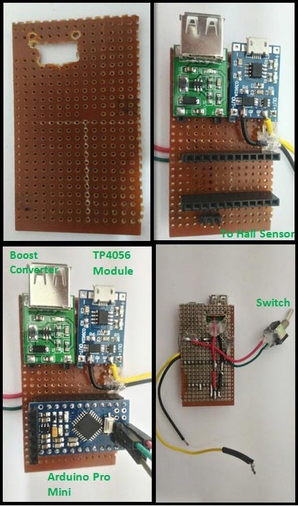
Once the connection is made, let us test the set up by using our 18650 Lithium battery. The lithium battery is highly explosive by nature, hence it must be handled with extreme caution. It is for this reason why we use a TP4056 Lithium Battery Charging Module. This module has over-charge/discharge protection and reverse polarity protection. Hence, the battery can be easily charged using a normal micro USB charger and can be safely discharged till it reaches the under voltage cut off limits. Some important details of the TP4056 charge module is given in the table below.
Parameters ----- Value per cell
Under-voltage cut-off ----- 2.4V
Over-voltage cut-off ----- 4.2V
Charging current ----- 1A
Protection: Over-voltage and reverse polarity protection
IC’s present: TP4056 (charger IC) and DW01 Protection IC
Indication LEDs:
- Red - Charging in Progress
- Green – Charge Complete
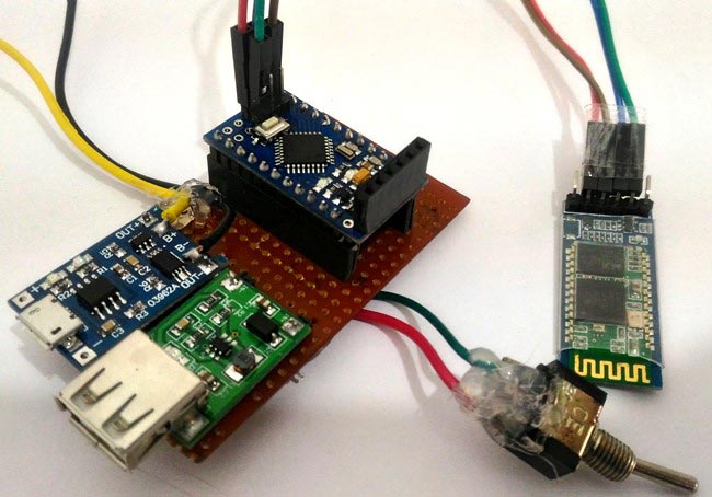
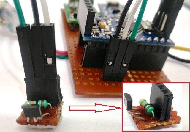
Now, let us start with the Hall Sensor Board. This board just contains two components: one is the 10K resistor and the other is the hall sensor. The connections can be made as shown in the schematics above. Once the board is ready, connect them using jumper wires as per the schematics. Once it is done, it should look something like this.
Another crucial step in the project is connecting the 18650 battery to the B+ and B- terminals of the TP4056 module using a wire. Since Li+ cells are explosive, it is highly not recommended to use a soldering iron over these cells. Although people have done it, it is highly risky and can easily end in a big mess. So the easy way to do it is to use magnets as shown below:
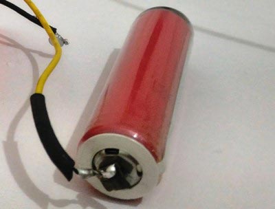
Simply solder the wire to a small piece of magnet and then stick the magnets to the terminals of the battery (they get attracted to terminals very well) as shown above. You might use some duck tap to further secure the position of the magnet.
Programming the Arduino:
The program for this project is very simple. We just have to calculate the speed of the rotating wheel by using the hall sensor interrupt inputs and broadcast the calculated speed over the air using Bluetooth module. The complete program is given in the Code section below and explained using the comment lines.
Each time the hall sensor detects the magnet it triggers an interrupt. This interrupt function is called by the magnet_detect()
function. This is the place where the rpm of the vehicle is calculated.
Once the rpm is calculated, the velocity of the wheel is calculated in the loop ()
function. Once the code is ready, let's dump it into our Arduino Pro Mini and test that it's working as shown in the video given at the end.
Android Mobile Application for Speedometer:
The Android application for this project is made using software called Processing. If you are not interested in making your own Android application and would like to just install the one used here, you can download the APK file and install it directly onto your smart phone by following the below steps.
1. You can directly download the APK file from the below link. This APK file is made for Android version 4.4.2 and above (Kitkat and above). Extract the APK file from the zip file.
Android Application for Speedometer
2. Transfer the .APK file from your computer to your mobile phone.
3. Enable installing application from Unknown sources in your Android settings.
4. Install the application.
If successfully installed, you will find the application named “Processing_code” installed on your phone as shown below:
Develop your own Application using Processing:
Either you can use the .APK file given above or you can build your own app using Processing as explained here. You can download the all the Processing Android application code from here. The program is self-explained using the comment lines. But if you have any problems or if you want to modify your application a bit, please use the comment section and I will help you out.
EXPANDED TECHNICAL DETAILS: Creating The Android Application in Processing
The Arduino only sends a data string like "25.4". The Smartphone does the heavy graphical rendering! Using the Processing IDE with the Android Mode enabled, you are writing raw Java. The Processing sketch opens the Bluetooth Socket, parses the incoming string until a newline '\n', converts it to a Float, and dynamically forces a virtual needle to sweep across a massive illuminated Digital Gauge rendered natively on the phone screen!
The Android program establishes a connection with our Bluetooth module during startup of the application and receives the speed of the vehicle which was calculated and broadcasted by the Arduino Pro Mini. I have created a small graphics also to display the speed using an analog speedometer to make it look a bit attractive. You can come up with your own ideas and tweak the code to personalise it for your needs. Also, check our other Processing projects to learn more about it:
- Ping Pong Game using Arduino
- Smart Phone Controlled FM Radio using Processing.
- Arduino Radar System using Processing and Ultrasonic Sensor
Once you have installed the application to your mobile phone, it's time to test our project. But we have not yet mounted our kit to a vehicle yet. Let’s do it.
Mounting the Speedometer kit to a vehicle:
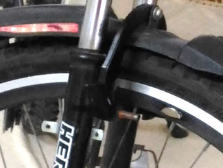
I have mounted this kit over my bicycle and tested it, and it works like a charm. Mounting the kit is left to your creativity, you can get your own small box from a shop and drill holes for the wires and connections and mounted it to your vehicle. One common important thing to note is that the magnet should be stuck to the rim of the wheel and the hall sensor should be mounted as close as possible to the magnet so that each time the magnet crosses the hall sensor, it should be able to detect it. The arrangement is shown below.
Since I have a 3D printer with me, I designed my own enclosures to make them look good and in way that it can be easily mounted and disconnected from our bike for charging the battery. So if you have a 3D printer or if you can gain access to one to print a few materials, continue reading, otherwise skip this part and use your own creativity to mount these things. Learn to user 3D printer here.
If you have decided to use my design files and print your enclosures, then make sure your main perf board is close to the below dimensions
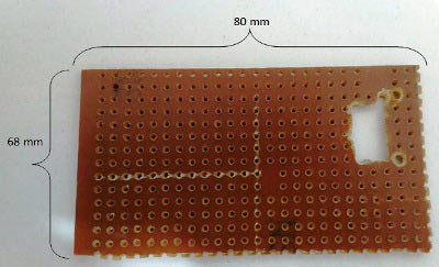
The complete Design and STL files for 3D printing can be downloaded from here. If the board is similar to what is have made here, then you can directly 3D print your enclosures using the given STL files or else you can use the Design files and modify it according to your board.
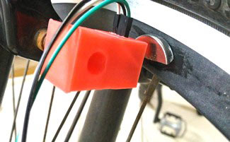
Let us start with the 3D printed small enclosure which will be used for the hall sensor module. Print the enclosure, place the circuit into it and harness your wires though the hole provided and then mount it to your vehicle so that the hall sensor is near the magnet as shown below.

ข้อมูล Frontmatter ดั้งเดิม
apps:
  - "1x Arduino IDE"
author: "user334153146"
category: "Sensors & Environment"
components:
  - "1x SparkFun FTDI Basic Breakout - 5V"
  - "1x 18650 Lithium cell"
  - "1x Soldering iron (generic)"
  - "1x HC-05 Bluetooth Module"
  - "1x Arduino Pro Mini 328 - 5V/16MHz"
  - "1x TP4056 Lithium battery module"
  - "1x 3V to 5V DC-DC Boost Converter with USB output"
  - "1x Headers (male and female)"
  - "1x Hall Effect Sensor"
  - "1x SparkFun Snappable Protoboard"
description: "High-speed kinematic tracking! Fuse brutal hardware rotational encoder interrupts natively with heavy serial string parsing to violently push absolute RPM velocity into an advanced dynamic Android dashboard rendered via the Processing framework."
difficulty: "Intermediate"
documentationLinks: []
downloadableFiles: []
encryptedPayload: "U2FsdGVkX1/LyUL0Wz0SphQhtj75b57GcXuIK2+wA6IR0UhRsvIDCv8uCvPRL28kAt6cyRfrfVuGTGcKjHlDA7uh/uZC5y5grvxguPlUNX0="
heroImage: "https://cdn.jsdelivr.net/gh/bigboxthailand/arduino-assets@main/images/projects/diy-speedometer-using-arduino-and-processing-android-app-ebc20b_cover.jpg"
lang: "en"
likes: 13
passwordHash: "e861fd34163e1cdf173d219a2af4841208720402c8176093180f2309a89cdba8"
price: 2450
seoDescription: "Create a DIY Speedometer for bikes and automotive using Arduino, Bluetooth, and an Android App."
tags:
  - "app development"
  - "mobile app"
  - "speedometer"
  - "automotive"
title: "DIY Speedometer Using Arduino and Processing Android App"
tools: []
videoLinks:
  - "https://www.youtube.com/embed/5xQN7-jQgpo"
  - "https://www.youtube.com/embed/EWPpe4cwfDY"
views: 39631