I am sure many of you also read about the IMLEC event which occurs in each year. I did and was fascinated. If you are not aware, this is an event where the efficiency of a locomotive is measured by using a Dynameter car behind a loco which is using a fixed amount of fuel and pulling a known weight.
This sparked my interest. How was this done? What magic pixies are inside this machine that make up a dynamometer car?
Research revealed a fascinating history of how a LNER dynamometer car was used to record No 4468 Mallard's speed record in 1938, and has been preserved at the National Railway Museum in York. If you are interested in this vehicle there is an excellent YouTube video by the York Railway museum on the car See link https://youtu.be/6x3TGPeImOc
As it turns out a dynamometer is very simple. The operating principle of the dynamometer car is based on the basic equation for power being equal to force times distance over time.
P = F x d / t
This equation can be reduced to power equals force times velocity:
P = F x v
On discovering this I suddenly occurred to me… WE CAN DO THAT! And we can do it cheap too!!
Historically this would have been done with a spring. (Think kitchen scales ) however due to cheap imported electronics we can do better and simpler. A Load Cell. With the modern cost of electronics being so cheap these days what would have been unachievable only a few years ago is now only £30. So off I went to eBay to buy one. Make sure you choose the correct applicable range. in our case for loco Dynamometer car testing 0-50Kg is just right.
How does a load cell work - Strain gauges are two wired organized metal foil or wires that are set up in such a way that the resistance changes when it is compressed or stretched. When a strain gauge is placed on something (usually metallic in nature) its resistance changes based on the stress experienced by that something.
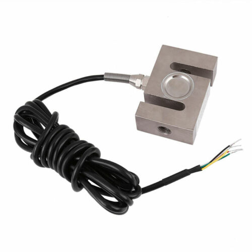
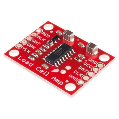
This is great for us. However, the change in resistance is very small. So in order for us to measure a sensible reading we use a loadcell amplifier HX711 (£6) to boost the signal.
Speed
For this we need to measure distance over time. My first thought here was to use a magnet attach it to a wheel of a bogie with a sensor (just the same as a speed sensor on a bicycles). This however in testing proved to be a poor solution as at low speeds I would receive lots of false positives from the sensor.
The alternative and more accurate option was to use a rotary encoder £11. This is a device that has a plate with holes located inside. As it rotates it allows light to pass through or not. We can measure these pulses of light to not only measure speed but also direction. The downside it to fit it to the bogie we have to add a pulley to the axles and timing belts. But this is only an inconvenience.
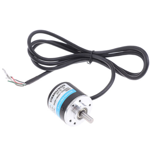
I chose a 100Pulses per revolution model (in practice this means 400 singnal changes as there is the rise and fall of two channels). We dont need too many pulses else we might reach the electronic limits of the arduino.
The Rest
With these two critical competent decided on we can add the remainder of the electronics to bring the whole design together.
Computer
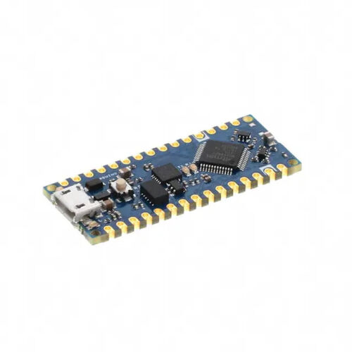
This was a simple choice for me. Arduino. I have the skills to program this and its small form factor.
However, I did choose the new latest model. Arduino Nano Every. This has a far higher clock speed than the older Nano and will be able to easily handle the pulses coming into the device. £18
Display and buttons
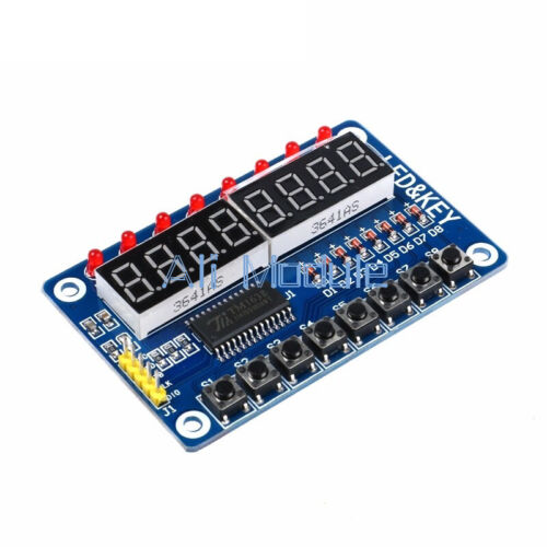
Another off the shelf device £6 LED & Key TM1638. We need a way to display the numbers this is a an elegant solution as we can have 8 number 8 lights and 8 buttons using only 3 wires.
Data Storage.
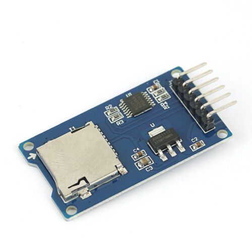
An SD card reader module £2. Again, a perfect solution for a cheap cost and simple wiring. Without having to design in all this functionality.
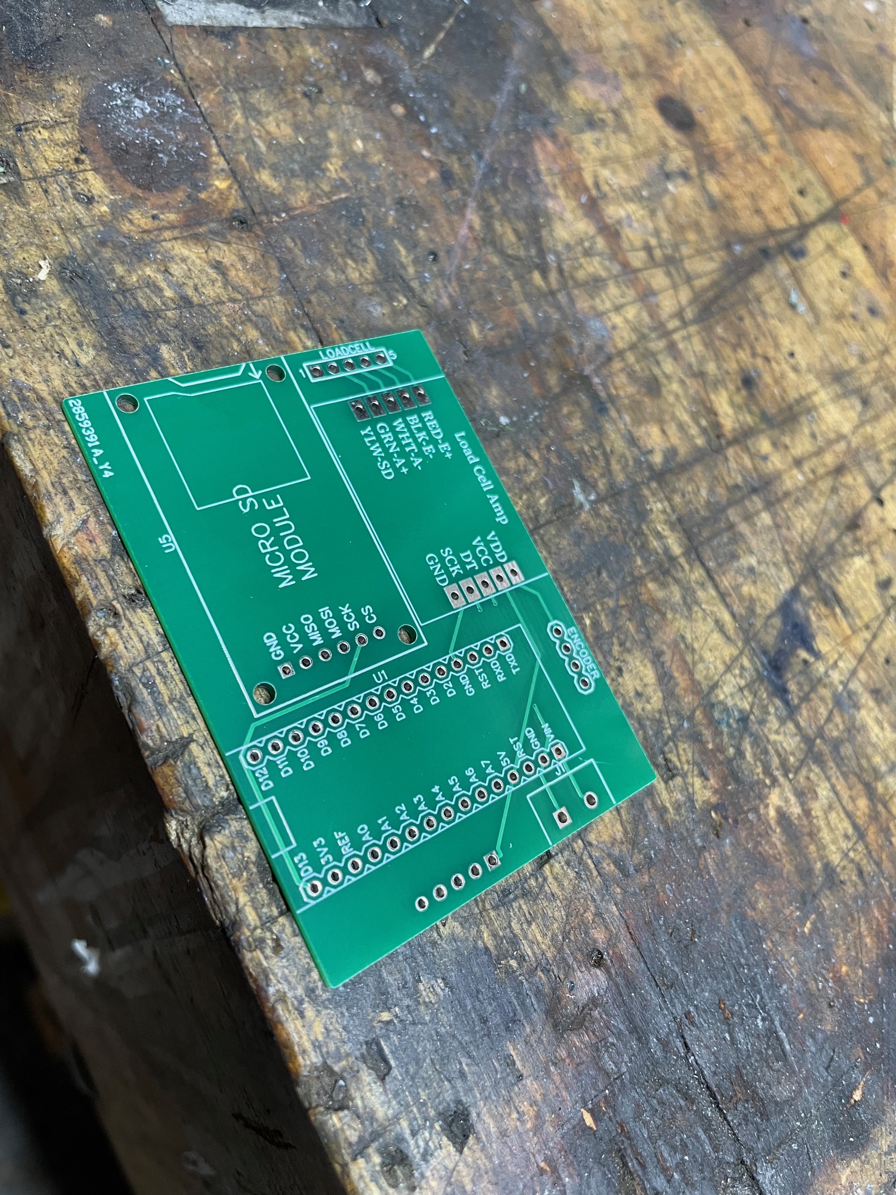
Electronics wiring design.
So we now just have to connect them all up. Here is the circuit design is attached to this documentation.
And subsequently due to cheap PCB manufacturing we can have a PCB made for only £3 (see easy eda file)
So currently I am £76 in. Plan here is to keep the rest of the project a cheap as possible.
Finding a bogie to fit this too is the most expensive part. I was unable to find one online for less than £200 which is not what I would like to spend. it was suggested by a friend we modify one of the riding trolleys for the club. So one of the trolleys was taken home for overall and a bit of TLC.
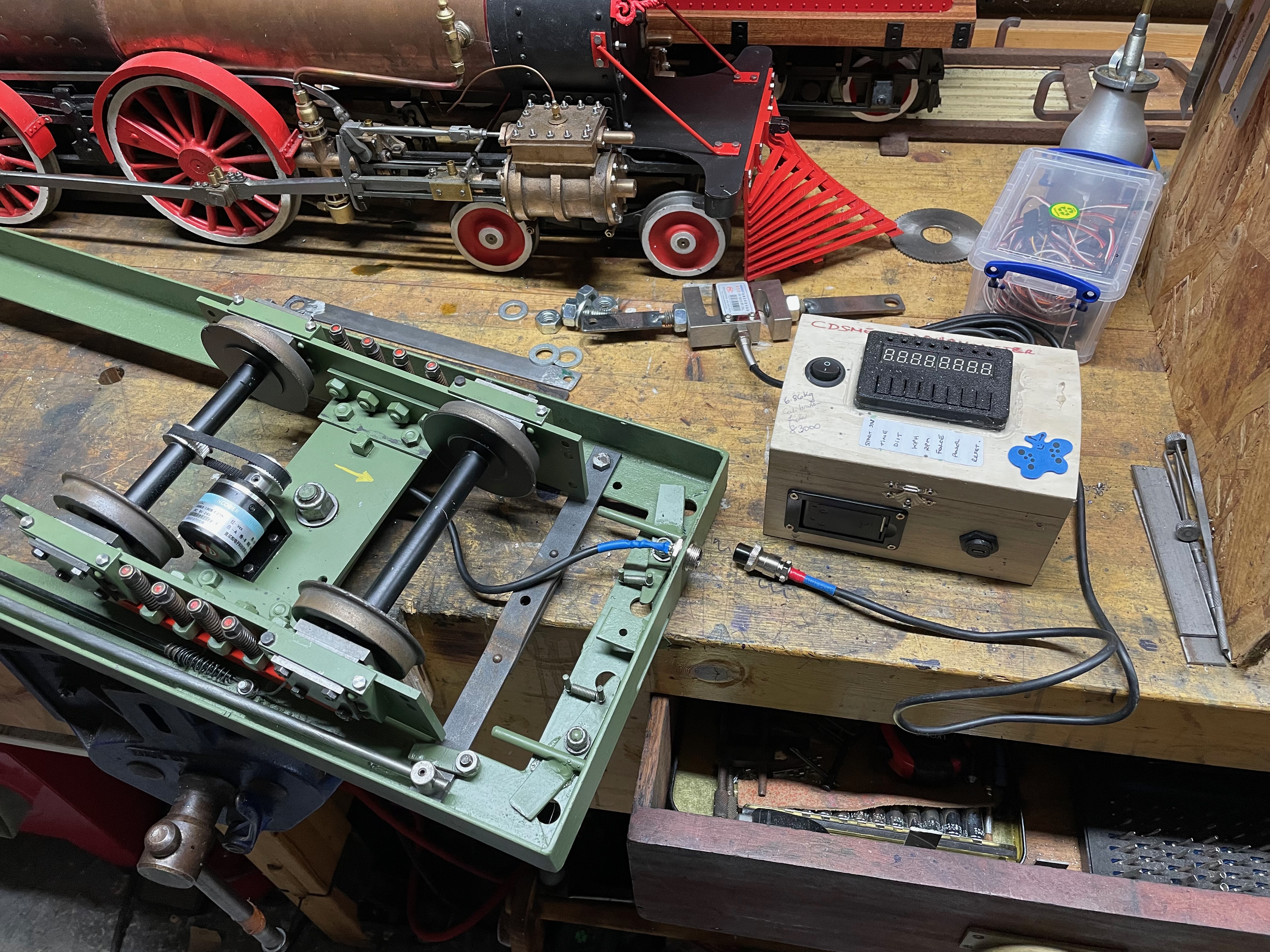
Pictures show the bogie removed cleaned and a fresh coat of paint encoder and load cell fitted.
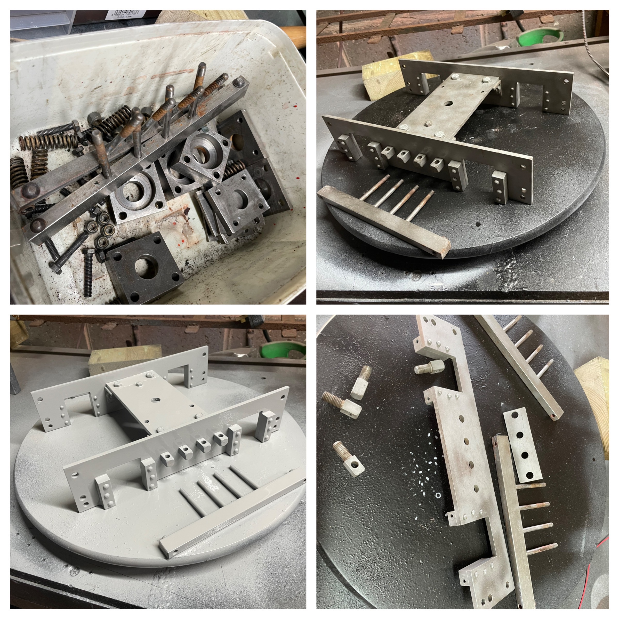
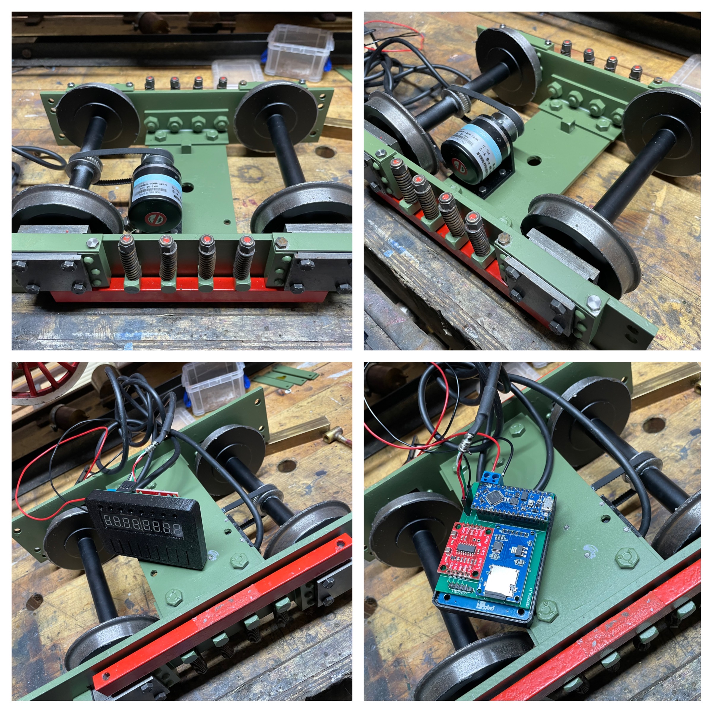
The dynamometer car fitted to one bogie and not fitted it back to the riding trolley, this allows for easy testing coding and calibration. Once happy with the design and software the Bogie can be fitted back to the trolley and the whole thing made back to normal riding trolley but with extra functionality.
EXPANDED TECHNICAL DETAILS
Force & Speed Measurement
A dynamometer car (or "Dyno Car") is used to measure the performance and pulling power of model trains or small vehicles.
- Strain Gauge / Load Cell: Integrated with an HX711 amplifier, it measures the drawbar pull (force) in grams or Newtons.
- Tachometer: An Infrared Interrupter or Hall Effect sensor on the wheels measures the RPM, allowing the Arduino to calculate the instantaneous speed.
Data Logging
- On-board Display: A small LCD shows real-time stats like Speed, Max Pull, and Distance traveled.
- SD Card Reporting: For professional analysis, data is recorded to an SD module in CSV format, allowing the user to plot performance graphs on a PC later.