Why I created this
At least a month ago my cousin said me to create a car so I thought really hard and made this
Note : it can be made with and without adafruit motor shield V2 and with and without shooters. App can be edited some ways of editing are shown in this tutorial.
Steps of working:
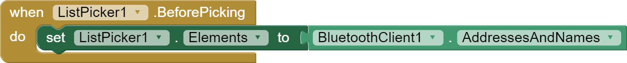
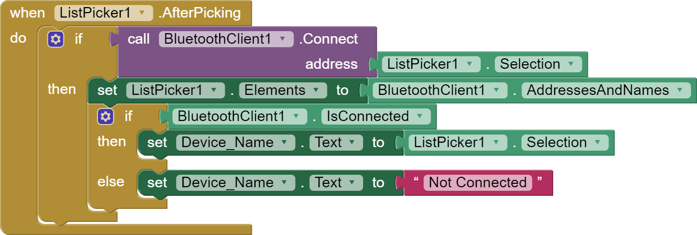
- App connects to bluetooth (Apk for app, Aia for app(import to MIT ai2))
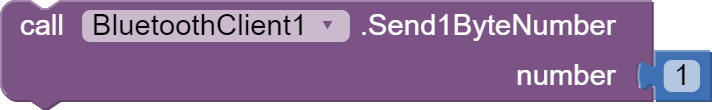
- app sends string to bluetooth
- arduino checks string
- and acts accordingly(front, back e.t.c)
Connections:
Using shield:
servo 1 and 2 are to be kept in default positions
motor should be in M1 and M4
HC-05 or 06 rx and tx should match line 2 :
SoftwareSerial mySerial(number of rxpinhere, numberoftxpinhere);
vcc and GND to 5v and GND
No shield:
servo 1 and 2 :
- vcc and GND to 5v and GND respectively
- orange pin for servo 1 to 9 and servo 2 to 10
motor1 should be in 2, 3
motor2 should be in 4, 5
HC-05 or 06 rx and tx should match line 2 :
SoftwareSerial mySerial(number of rxpinhere,numberoftxpinhere);
- vcc and GND to 5v and GND respectively
Code:
With shield:
Note: In line 2 number 52 and 53 have to mach connection of bluetooth order of connection isSoftwareSerial mySerial(RX,TX);:) Happy coding.
#include <SoftwareSerial.h>
SoftwareSerial mySerial(52, 53); // RX and TX can be edited
String BT_input;
int LED = 13;
#include <Servo.h>
Servo s;
Servo s2;
#include <AFMotor.h>
AF_DCMotor motor(1);
AF_DCMotor motor1(4);
void setup() {
 Serial.begin(9600);
 mySerial.begin(9600);
 s.attach(10);
 s2.attach(9);
 s2.write(0);
 s.write(0);
 pinMode(LED, OUTPUT);
 motor.setSpeed(255);
 motor1.setSpeed(255);
 motor.run(RELEASE);
 motor1.run(RELEASE);
}
void loop() {
 if (mySerial.available())
   {
       BT_input = mySerial.read();
       Serial.println(BT_input);
       if (BT_input=="1")
       {
         front();
       }
       if (BT_input=="3")
       {
         back();
       }
       if (BT_input=="2")
       {
         right();
       }
       if (BT_input=="4")
       {
         left();
       }
       if (BT_input=="5")
       {
         stop();
       }
       if (BT_input=="6")
       {
         shoot();
       }
       if (BT_input=="7")
       {
         shoot2();
       }
   }
}
void front(){
 motor.run(FORWARD);
 motor1.run(FORWARD);
}
void back(){
 motor.run(BACKWARD);
 motor1.run(BACKWARD);
}
void left(){
 motor.run(BACKWARD);
 motor1.run(FORWARD);
}
void right(){
 motor.run(FORWARD);
 motor1.run(BACKWARD);
}
void stop(){
 motor.run(RELEASE);
 motor1.run(RELEASE);
}
void shoot(){
 s.write(120);
 delay(100);
 s.write(0);
}
void shoot2(){
 s2.write(120);
 delay(100);
 s2.write(0);
}
No shield
Note: In line 2 number 52 and 53 have to mach connection of bluetooth order of connection isSoftwareSerial mySerial(RX,TX);:) Happy coding.
#include <SoftwareSerial.h>
SoftwareSerial mySerial(52, 53); // RX and TX can be edited
String BT_input;
int LED = 13;
#include <Servo.h>
Servo s;
Servo s2;
const int Motor_L_F = 2;
const int Motor_L_B = 3;
const int Motor_R_F = 4;
const int Motor_R_B = 5;
void setup() {

}
void loop() {
 if (mySerial.available())
   {
       BT_input = mySerial.read();
       Serial.println(BT_input);
       if (BT_input=="1")
       {
         front();
       }
       if (BT_input=="3")
       {
         back();
       }
       if (BT_input=="2")
       {
         right();
       }
       if (BT_input=="4")
       {
         left();
       }
       if (BT_input=="5")
       {
         stop();
       }
       if (BT_input=="6")
       {
         shoot();
       }
       if (BT_input=="7")
       {
         shoot2();
       }
   }
}
void Forward(){
 digitalWrite(Motor_L_F, HIGH);
 digitalWrite(Motor_L_B, LOW);
 digitalWrite(Motor_R_F, HIGH);
 digitalWrite(Motor_R_B, LOW);
 }
void Right(){
 digitalWrite(Motor_R_F, LOW);
 digitalWrite(Motor_R_B, HIGH);
 digitalWrite(Motor_L_F, HIGH);
 digitalWrite(Motor_L_B, LOW);
 }
void Left(){
 digitalWrite(Motor_L_F, LOW);
 digitalWrite(Motor_L_B, HIGH);
 digitalWrite(Motor_R_F, HIGH);
 digitalWrite(Motor_R_B, LOW);
 }
void Back(){
 digitalWrite(Motor_L_F, LOW);
 digitalWrite(Motor_L_B, HIGH);
 digitalWrite(Motor_R_F, LOW);
 digitalWrite(Motor_R_B, HIGH);
 }
void Stop(){
 digitalWrite(Motor_L_F, LOW);
 digitalWrite(Motor_L_B, LOW);
 digitalWrite(Motor_R_F, LOW);
 digitalWrite(Motor_R_B, LOW);
 }
void shoot(){
 s.write(120);
 delay(100);
 s.write(0);
}
void shoot2(){
 s2.write(120);
 delay(100);
 s2.write(0);
}
Edit app:
Note
There are some ways you can edit the app :
- Designer
- blocks(programming)
first we need to upload the aia (adobe in action) in http://ai2.appinventor.mit.edu :
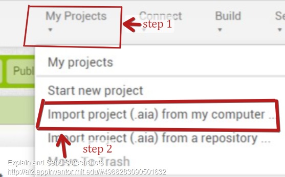
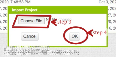
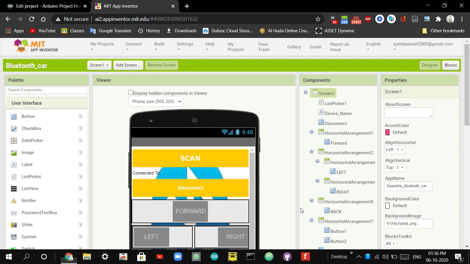
after uploading the app you can play around with the designs images and more
if you want to remove shooting you can simply delete the button.
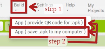
well after editing you can export project to apk using 2 methods
- qr code
- apk to computer
Both options can be found in the build tab.
EXPANDED TECHNICAL DETAILS
Drag-and-Drop Robotics Hub
This project lowers the barrier to entry for mobile robotics by combining Arduino hardware with the visual programming power of MIT App Inventor 2.
- Bluetooth Serial Stream: The Arduino (using an HC-05 or HC-06) receives single-character "Triggers" (like 'F', 'B', 'L', 'R') from the custom-built Android app.
- L298N Motor Drive: The Arduino handles the Pulse Width Modulation (PWM) duty cycles for two DC motors. Because the app uses a visual joystick, the user can control the car's speed proportionally based on how far they move the virtual stick.
Rapid App Deployment
- UI Design: The MIT App Inventor project features a custom layout with branding and diagnostic readouts, allowing students to see exactly how mobile software and robotics hardware communicate in real-time.