Innovation
So I had always wanted to build a gesture controlled car. I searched up many tutorials, but SO MANY of them made them complicated. So i designed this one myself. And you know what's better? This project is universal(more about it later).
Tutorial
Lets start.
Receiver part( The car)
So first of all, you will require a chassis. You can order one online. Not too complicated. Or if you are a amateur, you can stick with cardboard/canvas/acrylic and glue guns anyways😅.
In this project, I have used two boards- one for receiver, another for transmitter.
2 nRF2401 transceiver module, one for the transmitter board, another for the receiver. I have used the standard nRF2401 modules. They have a nice range.
First of all, assemble the motors with their wires. If you are seeing this tutorial, I expect you don't need a tutorial for this segment.😅
If you are using 4 motors, wire both the negative and the positive terminals of both motors together, so you can connect both through 2 wires, like if it was only one motor.
(note: l298n supports only 2 motors. So this is necessary. If you are using l293d, u can look up tutorials to control through l293d.)
Then connect the 2 pairs of motor as shown in the schematic at the end.
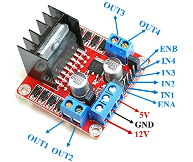
For arduino uno and l298n,
digital pin 2 > IN1
digital pin 3 > IN2
digital pin 4 > IN3
digital pin 5 > IN4
AND The power connection part is very important. I have found that connecting Arduino to the 5v slot and gnd slot of l298n does not power it up well. Datasheets mention operating voltage 6v to 12v, so why?
So, The slot labeled 12v, You have to connect the positive terminal of battery to it AND ALSO in the same slot a wire, which connects to VLN pin of Arduino. The connect the battery's negative terminal to gnd, and also a wire in the same slot, which connects to anyone of the GND pin on arduino.
The L298N Differential Action Matrix
The Receiver block bounds identically to the RC chassis frame. The receiving nRF24L01 module actively parses the incoming data stream. When a command like 'L' is received, it triggers differential steering. Because there is no steering tire mechanism on a standard 4WD chassis, it utilizes Tank Steering. The C++ commands the L298N Motor Driver to execute this. For example, to turn left, the right-side motors are driven forward while the left-side motors are driven backward, causing the car to pivot on its central axis, mirroring the twist of the operator's wrist.
Now, let us connect nRF2401 module to UNO.
pinout:
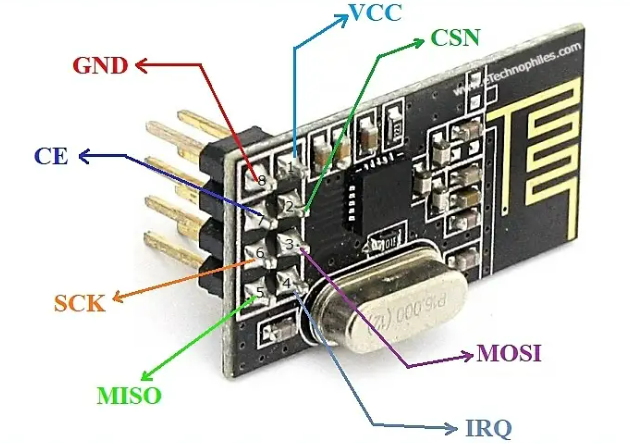
Note that You don't need to connect IRQ to anything.
WARNING: POWER ONLY THROUGH 3V3 AND NOT THE 5V ON THE ARDUINO BOARD, OR IT MAY RENDER MODULE USELESS.
Connections:
arduino nRF2401
GND > GND
3V3 > VCC
digital 8> CSN
digital 7> CE
digital 11> MOSI (spi interface)
digital 12> MISO (spi interface)
digital 13> SCK (spi interface)
The SPI interface pins are the default pins. The CSN and CE pins can be any digital pins, but u will need to change it accordingly in the code.
Transmitter part:
Here I used ESP32 ( DOIT ESP32 Devkit v1). There are two modules The ESP will be connected to - nRF2401 (which will send data to its corresponding partner on the receiver.)
Connect the nRF2401 like this-
esp32 nRF2401
GND > GND
3V3 > VCC
d15 > CSN
d2 > CE
d23 > MOSI (spi interface)
d19 > MISO (spi interface)
d18 > SCK (spi interface)
Now is the right time to mention why it is universal. You must have noticed that the transceiver modules always connect to the respective SPI interfaces of the board. like on esp, MOSI is d23, and like that. Many tutorials use integrated rf modules. But in this project, if you have ANY TWO micro controller boards supporting I2C and SPI interface, which comes in maximum boards today. You can power the module, and connect the respective interface (nrf and the mpu6050)
Lets continue.
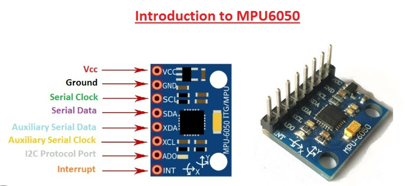
Connect the mpu 6050 as follows to esp
esp mpu6050
d21 > SDA
d22 > SCL
and the gnd and 3v3. cmon u expect me to tell how to power again and again?
(rest 4 pin don't need to be used in this project. if u see u have only one 3v3. if u want to connect , just connect the 3v3 of nRF and mpu6050 together then one wire from the join to the 3v3.)
The Smart Glove Geometry (MPU6050)
The Transmitter block is entirely mounted on a cloth glove. An MPU6050 6-Axis Accelerometer sits on the back of the hand. The ESP32 reads its X/Y acceleration vectors. When the human wrist is tilted forward, the Y-axis acceleration surpasses a positive threshold (e.g., > 15000), triggering a 'Forward' command. When the wrist is banked intensely to the left, the X-axis acceleration falls below a negative threshold (e.g., < -15000), triggering a 'Left' command. The transmitter then immediately sends this command character via the nRF24L01 module continuously into the radio spectrum.
I am leaving the part of designing a glove and embedding the hardware into it to you, as u may want to design as per convenience. I know esp is a overkill, but i did not have any other board of that form factor. and as mentioned, u can connect any board.
To program ESP32 , u need to install board manager for that, cuz u cannot program the esp in a newly installed ide directly. Tutorial for that on this link
credits- Electronics HUB
How to operate the project-
After turning on both the car and remote, the nRF on both sides should be connected. Wait for about 20 seconds, for the mpu6050's accelerometer to calibrate. Because the mpu is the module that will track the movement of your hand.
Once calibrated, tilting the mpu6050 module forward will make the car go forward. Tilting it towards yourself, or backwards, will make the car go backwards. Tilting towards the left or right correspond to the same function also.
Troubleshooting-
-Check if you have wired the nRF modules on both sides correctly.
-Please use a Li ion rechargeable battery if possible. I had trouble using alkaline batteries.
-Wait 20 seconds for mpu to calibrate.
-If the transmission is working, but different actions are being executed- i.e on tilting forward the car is going backward, then interchange the pins of l298n to arduino like this-
pins of 2,3 -> 3,2
pins of 4,5 -> 5,4
You would have noticed that i just reversed their polarity. same like this, if the car is going left instead of right and vice versa,
pins of 2,3 -> 4,5
pins of 4,5 -> 2,3.
-Check the power supply also.
- CONNECT TO 3V3 ONLY THE NRF MODULE!!!
- Don't be too far away, or check for any obstruction or interference in radio transmission.
I think this much is enough
Code and schematics-
Now here is the Schematics and the code: I will add a video soon.
Bionic Telemetry Rig
- Transmitter (The Glove): ESP32 + MPU6050 + nRF24L01 + battery.
- Receiver (The Vehicle): Arduino Uno + nRF24L01 + L298N Heavy Duty Motor Driver.
- A generic 4WD chassis frame kit (Mandatory 4 motors; 2WD does not pivot well on carpet surfaces).
- A 7.4V to 11.1V Lithium-Polymer Battery Pack explicitly dedicated solely into the heavy L298N 12V power terminal (to prevent the Uno logic from browning out).