Designing and Building a "Digital Dice" with 7-Segment and Light Sensor (LDR)
About this project:
This is an easy Digital Dice project using a one-digit 7 segment display. It is so simple because all you need to do is touch the top of the photoresistor (LDR). It demonstrates the principles of Embedded Systems by switching from traditional push buttons to using a "shadow" or touching/covering the LDR with your finger to command the dice to randomize a number.
If you would like to see how it works, go ahead and click on this link!
A Deep Dive into the 1-Digit 7-Segment Display
1-digit 7 segment display breakdown:
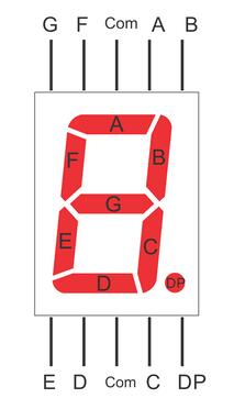
A 7-segment display consists of 7-8 LEDs (including the decimal point or DP) arranged in the shape of the number 8. To display any number, we need to control the on/off state of each LED segment according to a specific pattern. Each segment is labeled with a different letter and connected to light up a different LED in the display. I will be referencing this to explain the connections (ex. C goes to Pin 5). Understanding this structure is crucial because if even one pin is connected incorrectly, the displayed number will be distorted immediately.
Hardware Implementation Details
In this project, we have two main interconnected parts: the Input Sensing section and the Output Display section.
1. LDR Sensor Section (Photoresistor)
An LDR is a sensor whose resistance changes with the intensity of incident light. For Arduino to read this value, we must set up a Voltage Divider circuit as follows:
- Photoresistor/LDR first pin is connected to 5V.
- Photoresistor/LDR second pin is connected by a 10 KΩ resistor to GND, also the same pin is connected to A0 on the Arduino Uno.
When you cover the LDR with your hand, its resistance increases, causing the voltage across the 10 KΩ resistor to decrease. Arduino will detect this change in the Analog value and use it as a trigger signal to randomize a number.
2. 7-Segment Display Section
To drive the LEDs in the display, we need to use Current Limiting Resistors to prevent damage to the LEDs:
- The1digit7segmentdisplay is connected by multiple 220Ω resistors to various pins.
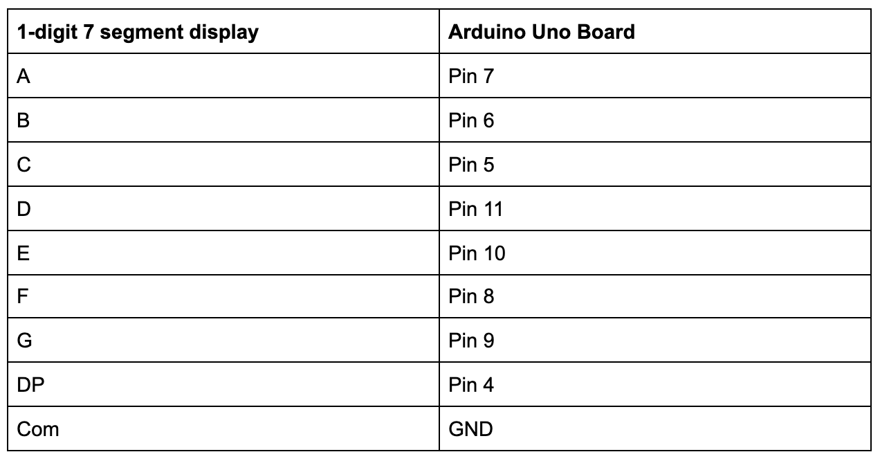
- Those are the specific connections. Refer above to see what the letter pins on the display refer to.
Software Logic Analysis
The core of this project lies in converting the Analog value from the LDR into a number randomization event.
- Calibration: Lighting conditions vary in each room. You should fine-tune the Threshold value in the code for the project to work as accurately as possible. NOTE: You can configure the lighting in the code to the lighting in your room. Just use this link to figure out your photoresistor readings.
- Randomization: When the value read from
analogRead(A0)falls below the set threshold (due to a shadow covering it), the program will call therandom(1, 7)function to randomize a number from 1 to 6. - Display Logic: After obtaining the random number, the code will use the
digitalWrite()command to send signals to various ports according to the patterns defined in the sub-function (e.g., if the number 1 is randomized, segments B and C must be set to HIGH).
Technical Pro-tips:
- Component Saving: If you do not want to use 8 220 Ω resistors, you can change all of the HIGHs in the digitalWrite(, HIGH); to a DEFAULT: digitalWrite(, DEFAULT);. These will be in the if statements and will set the LEDs in the segments to a medium level so the display won't burn out. :) Alternatively, you can reduce the display brightness to protect the LEDs by switching from a normal
HIGHstate to using PWM techniques. - Debouncing: At an engineering level, adding a small delay after detecting light helps prevent redundant randomizations caused by light noise.
This project serves as an excellent starting point for learning Input/Output management and the creative application of sensors in everyday life!