Controlling and Transmitting Data via WiFi with Arduino and ESP-01
Introduction and Project Concept (The Concept)
In the world of IoT (Internet of Things), wireless device control is often costly and complex. This project aims to create a control unit that operates via a WiFi network, focusing on maximum economy and efficiency. The result is a system capable of controlling up to 10 output channels (On/Off) and reading analog input values from up to 8 sensor channels to monitor various conditions in an area in real-time.
At the heart of this project is the ESP-01 WiFi module from Espressif Systems, considered the cheapest add-on module for Arduino on the market (approximately 60-70 Baht). Despite its small size, it offers strong internet connectivity capabilities.
For in-depth use, you can refer to the programming manual (AT Instruction Set) from the Espressif website, titled 4a-esp8266_at_instruction_set_en.pdf, which covers the module's usage commands in Modem (AT Mode) as we use it in this project.
The main control board we use is Arduino UNO R3, as it has comprehensive connection ports and is beginner-friendly. However, this project is designed to be flexible enough to be adapted for use with other Arduino family boards such as Nano or Mega.
Technical Challenge: Since Arduino UNO has only one Hardware Serial port (which is used by USB for programming and debugging), we cannot connect the ESP-01 directly to that port, as it would cause data collisions. Therefore, we chose to use the SoftwareSerial.h library to emulate Digital pins 2 and 3 as an alternative Serial Port for communication with the WiFi module.
Hardware Structure and Assembly (The Hardware)
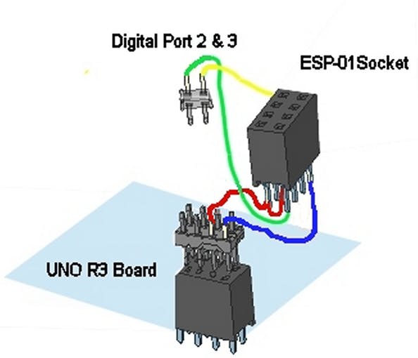
To ensure a robust and easily detachable connection between the Arduino UNO and the ESP-01, I created a special "Bracket" or mounting base using a Stripboard and Pin Headers that plug directly onto the Arduino board to draw 3.3V power and GND.
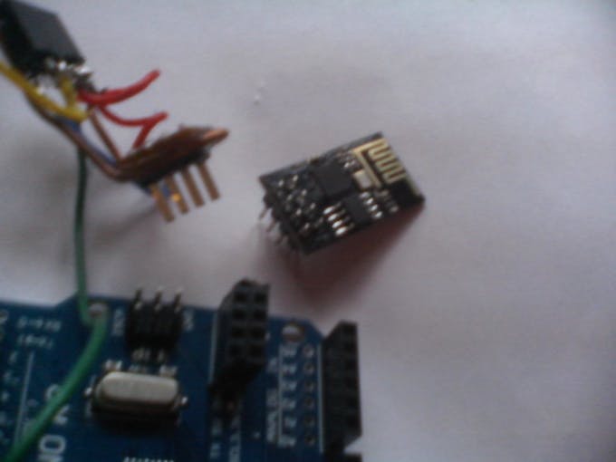
Since the ESP-01 module has 8 pins arranged in two rows, I used a dual-row socket soldered onto the Stripboard with the copper side facing up to easily connect wires between the socket and the pins that will plug into the Arduino board.
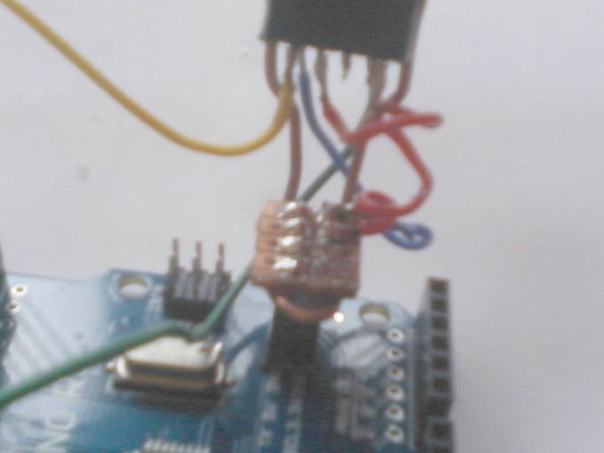
Additionally, I used thick copper wire bent into a support frame and coated with Epoxy Resin to help reinforce the structure, making it durable for repeated insertion and removal, and preventing damage to the signal pins.
Circuit Connection (Pin Mapping):
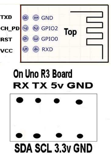
- ESP-01 Pin 1 (GND): Connect to Arduino's GND
- ESP-01 Pin 5 (VCC): Connect to 3.3V power only (never connect 5V)
- ESP-01 Pin 7 (CH_PD / EN): Connect to 3.3V to enable the chip
- ESP-01 Pin 8 (TX): Connect to Digital Port 2 (SoftwareSerial RX)
- ESP-01 Pin 4 (RX): Connect to Digital Port 3 (SoftwareSerial TX)
Important Caution: The ESP-01 module operates at 3.3V for both power supply and logic signals. Connecting it directly to 5V may cause permanent damage to the module.
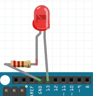
For output testing, I used an LED connected via a 1K Ohm resistor to ground. This helps visualize the operation when on/off commands are received over the network.
Software Analysis and Operational Logic (The Software)
This program is designed to turn the ESP-01 into an Access Point (AP) and TCP Server, with the Arduino sending AT Commands to the module to configure the entire network system.
Code Logic Operation:
1. Initialization (Setup): The program starts by disabling Echo (`ATE0`), setting the mode to Access Point (`CWMODE=2`), assigning the IP as `192.168.5.1`, and opening a TCP Server on Port 80.
2. Loop Monitoring: The Arduino continuously monitors incoming data via Software Serial. If data is received, it is sent to the `readFromWifi()` function to convert it into a String and uppercase it for easier checking.
3. Command Parsing:
- HELLO: Responds with connection status
- LEDON: Turns on the LED on pin 13 (Built-in LED)
- LEDOFF: Turns off all Digital Outputs (pins 4-13)
- LEDONNxxxx: An advanced command using Bitwise Operation to control 10 outputs simultaneously, by sending a 4-digit number to convert into the logic state for each pin.
4. Data Feedback: Each time a command is issued, the system calls the `Sensor_Read()` function to read Analog A0-A7 values and send them back to the Client to confirm the current status of the device.
// Important Code Snippets
#include <SoftwareSerial.h>
int serialRx = 2;   // Software Serial RX
int serialTx = 3;   // Software Serial TX
SoftwareSerial portOne(serialRx, serialTx);

void setup() {
  portOne.begin(115200); // Initialize communication with ESP-01
  delay(200);
  sendToWifi("ATE0",100);  // Disable command echo
  sendToWifi("AT+CWMODE=2",10); // Set as Access Point
  sendToWifi("AT+CIPAP_CUR=\"192.168.5.1\"",10); // Assign board IP
  sendToWifi("AT+CIPSERVER=1,80",10); // Open Server Port 80
}
How to Use with a TCP Client
After successfully uploading the code to Arduino, you can control the board by following these steps:
- Connect to WiFi: On your computer or smartphone, search for the WiFi network named "ESP8266" and enter the password "1234567890".
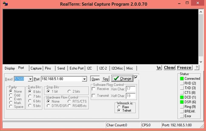
- Open a TCP Client program: You can use a program like Realterm (on PC) or a TCP Client app (on Android/iOS).
- Configure connection settings: Specify the IP Address as
192.168.5.1and Port as80. - Send control commands:
Example System Response:
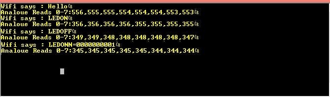
- When sending
HELLO: The board will reply "Wifi says : Hello" along with the status of 8 analog channels. - When sending
LEDONN0001: The board will turn on the light on pin 4 and reply with a binary number to confirm the status of all pins. - Analog Reads 0-7: data will always be sent back after every command, with each pin's value separated by a comma, making it easy for the receiving program to process.
Additional Recommendation: This project is designed to be as simple as possible using the standard Firmware that comes with the ESP-01. If you require higher response speed, it is recommended to disable all Serial.print commands used for debugging, as this will reduce the Response Time from 25 seconds to approximately 5 seconds.