ESP8266 - Setup and First WiFi Connection
ESP8266 - Sunbathing
If you've just got an ESP8266 module in your hands but are still confused about how to get started or how to make it work with your projects, don't worry! I've been there before, and today I'm going to share some basic usage techniques that will turn a difficult task into an easy one. This article is a complete guide to help you take your first steps into the world of IoT (Internet of Things) and professionally connect your projects to a WiFi network.
(For anyone interested in exploring more advanced ESP8266 projects, you can visit the blog virginrobotics.blogspot.com)
Why ESP8266?
If you've ever dreamed of controlling your projects over the internet, whether it's operating a servo motor, turning LEDs on/off, or building a small Smart Home system, the ESP8266 is the key to making that dream a reality. It functions similarly to a Bluetooth module like the HC-05 but is much more complex and powerful, as it can take your projects beyond distance limitations via wireless networks.
For beginners, the ESP8266 might seem difficult to use at first (I struggled with it for months myself!). But this article will summarize only the essential content and the fastest way to get it working.
Hardware Requirements
Before you start, you'll need these components for the system to operate stably:
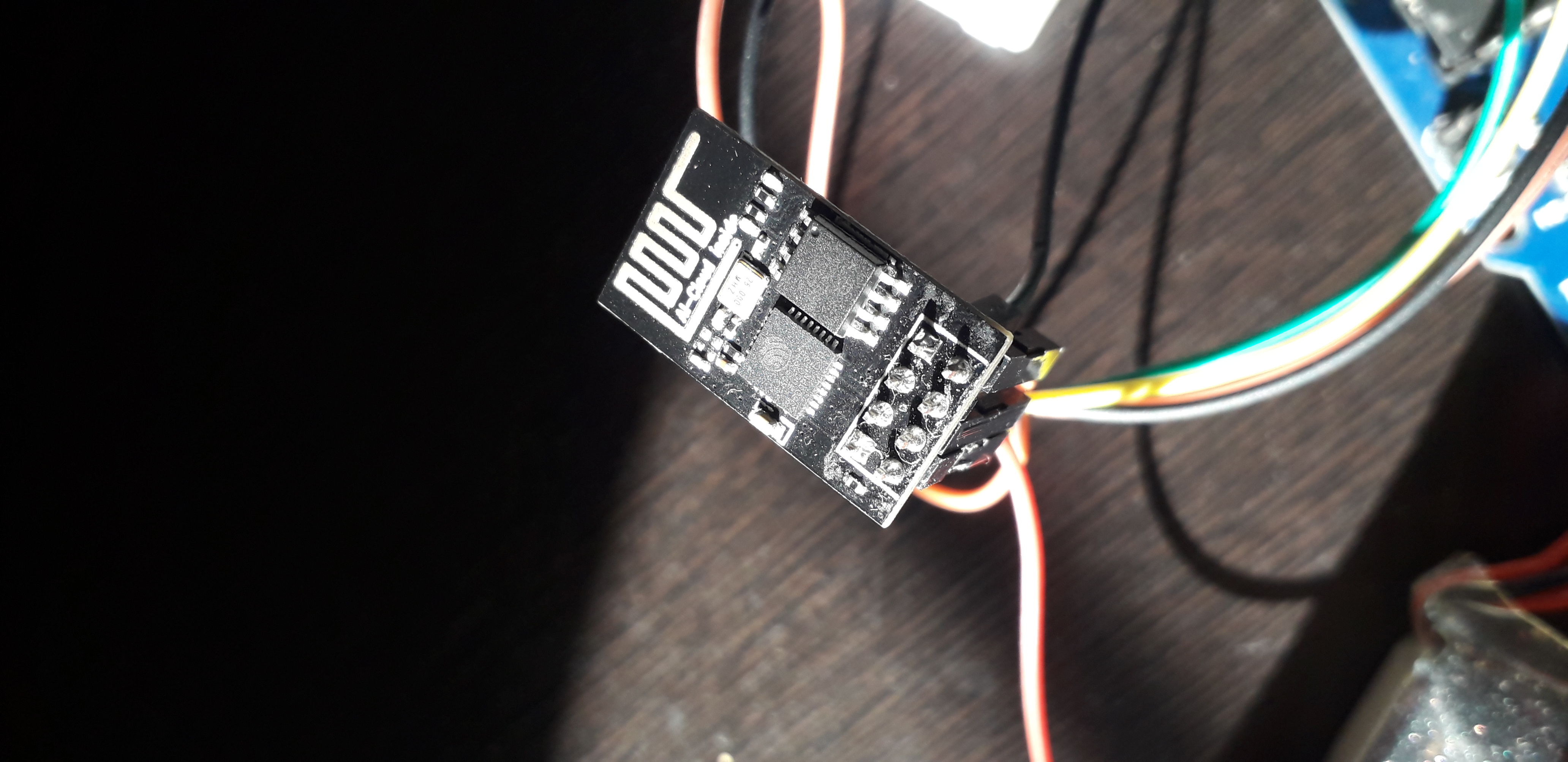
- ESP8266 Module (ESP-01 model): The star of the show.
- 1k Ohm Resistors (3 pieces): Used to create a Voltage Divider to reduce the TX signal voltage from the Arduino (5V) to 3.3V, preventing module damage.
- Breadboard Power Supply Module: (Highly recommended) Because the ESP8266 consumes high current during WiFi data transmission (up to 200-300mA), and the 3.3V pin on an Arduino board often cannot supply enough current, causing the module to reset frequently.
- Arduino UNO Board: Used as an intermediary for communication and programming.
- Jumper Wires (Male to Male & Female to Male)
- Breadboard
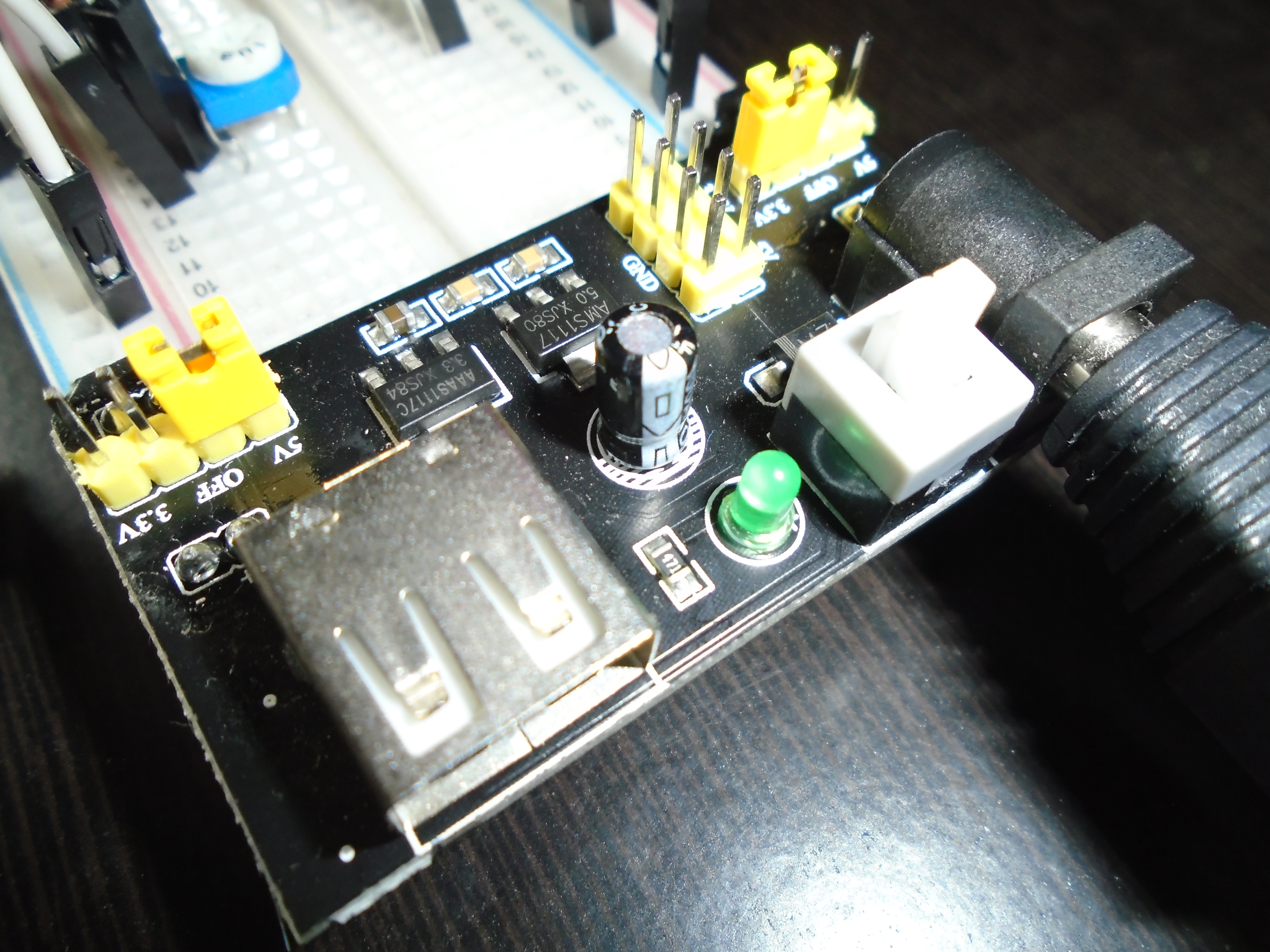
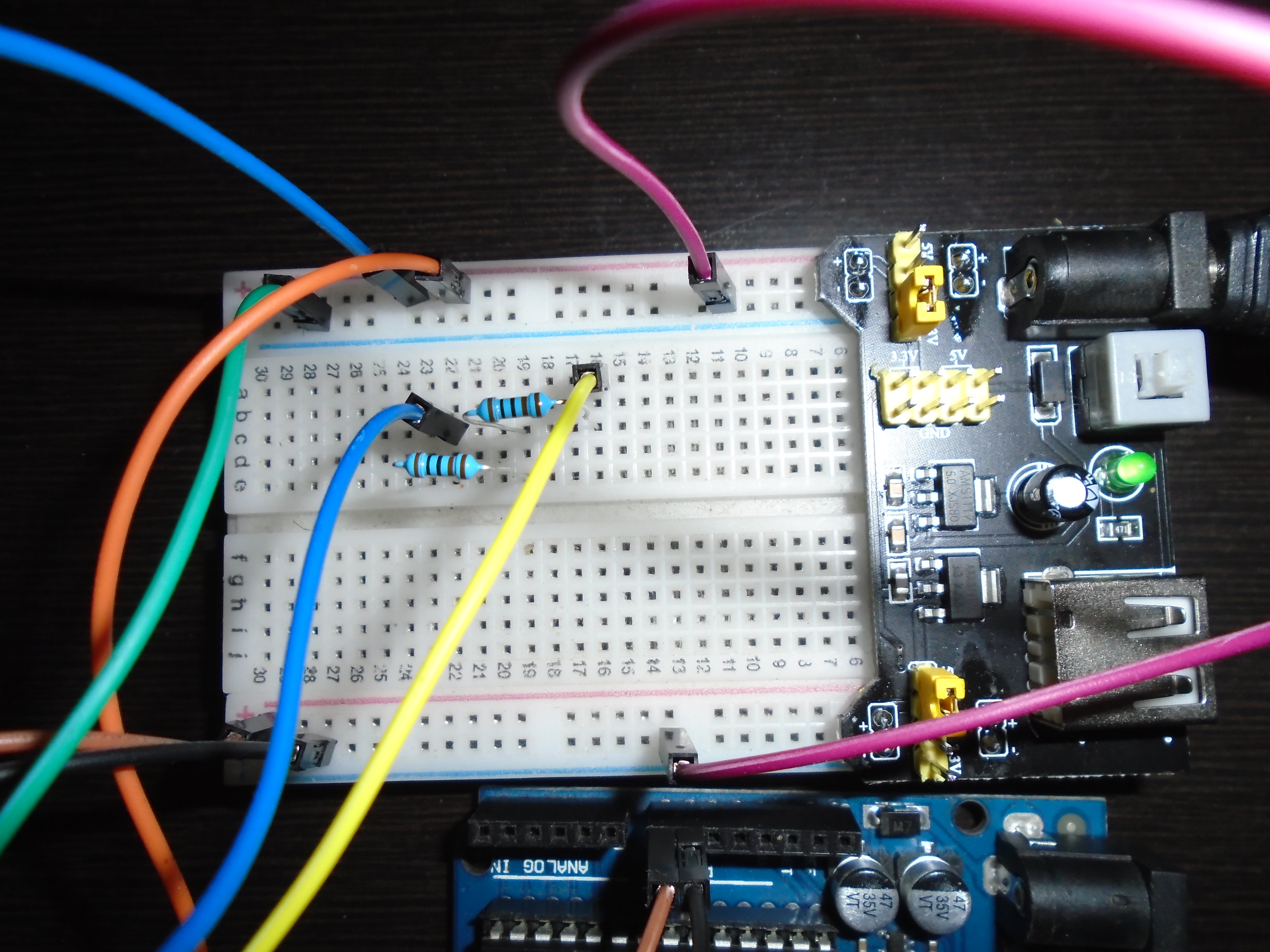
Separating 5V and 3.3V power rails on a Breadboard for safety.
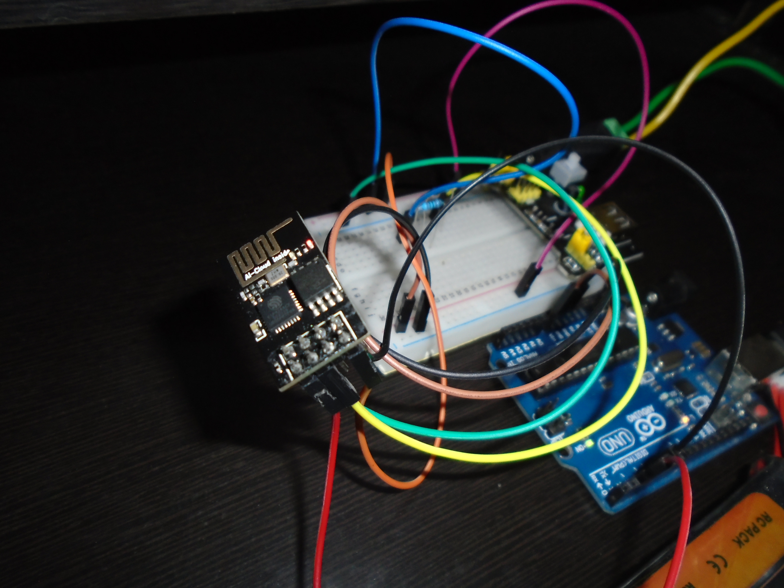
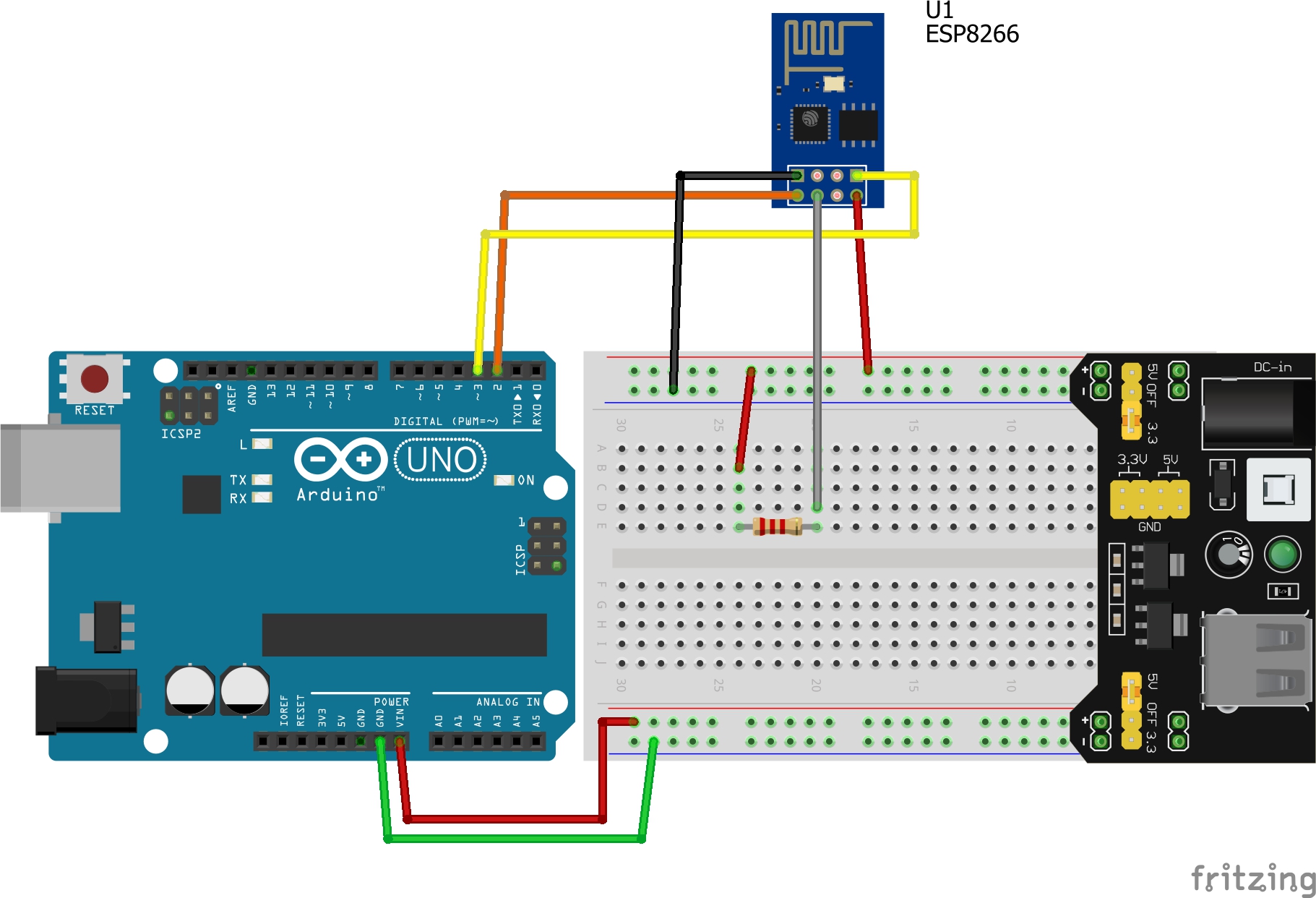
Circuit Assembly
Important Warning: The ESP8266 operates at 3.3V only. Never connect 5V from the Arduino directly to the VCC pin or send a 5V Logic signal directly to the RX pin, as this will instantly damage the module!
Important Pin Details:
- VCC: Connect to 3.3V (from a separate power source).
- GND: Connect all Grounds together.
- CH_PD (Enable): Must be connected to 3.3V to enable the module.
- TX: Connect to Arduino Pin 2 (via SoftwareSerial).
- RX: Connect to Arduino Pin 3 (must go through a Voltage Divider circuit to reduce to 3.3V).
Note: For power supply, the Arduino board can receive power from the Vin pin if you are using an external power source.
The Source Code
We will use the Arduino as a "bridge" for communication between the computer's Serial Monitor and the ESP8266, using the SoftwareSerial library to separate the communication pins from the normal Hardware Serial.
#include <SoftwareSerial.h>

// Define RX and TX pins for communication with ESP8266
// Arduino Pin 2 (RX) connects to ESP8266's TX
// Arduino Pin 3 (TX) connects to ESP8266's RX (via Voltage Divider)
SoftwareSerial ESPserial(2, 3);

void setup()
{
  // Initialize Serial Monitor at 115200 baud
  Serial.begin(115200);

  // Initialize Software Serial for ESP8266
  // Factory default is usually 115200 baud
  ESPserial.begin(115200);

  Serial.println("");
  Serial.println("Remember to set Both NL & CR in the serial monitor.");
  Serial.println("Ready");
  Serial.println("");
}

void loop()
{
  // Read data from ESP8266 and send to Serial Monitor
  if ( ESPserial.available() )   {  Serial.write( ESPserial.read() );  }

  // Read commands from Serial Monitor and send to ESP8266
  if ( Serial.available() )       {  ESPserial.write( Serial.read() );  }
}
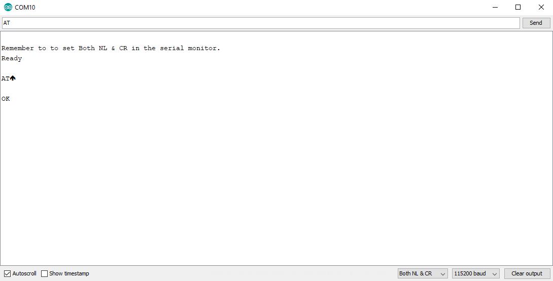
Testing with AT Commands
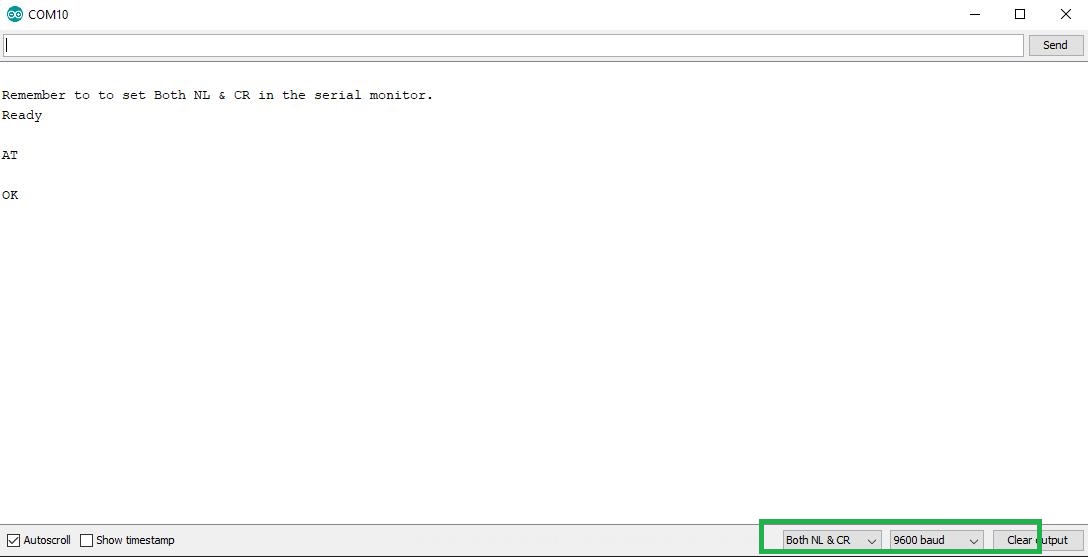
Once the code is uploaded, open the Serial Monitor and set the bottom right to "Both NL & CR" at a speed of 115200 baud.
- Type
ATand press Enter. - If the module is working correctly, it will respond with
OK.
Step 1: Changing the Baud Rate
Since SoftwareSerial does not work very stably at 115200 baud (which may result in garbage data), we should change the ESP8266's speed to 9600 baud for maximum accuracy.
Send the command:
AT+UART_DEF=9600, 8, 1, 0, 0
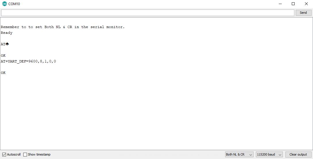
If you receive OK, the speed has been changed. Now the data on the screen will become unreadable because the speeds don't match. Close the Serial Monitor and go back to modify the code in the Arduino IDE:
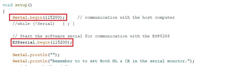
Change both Serial.begin(115200) and ESPserial.begin(115200) to 9600. Then upload the code again.
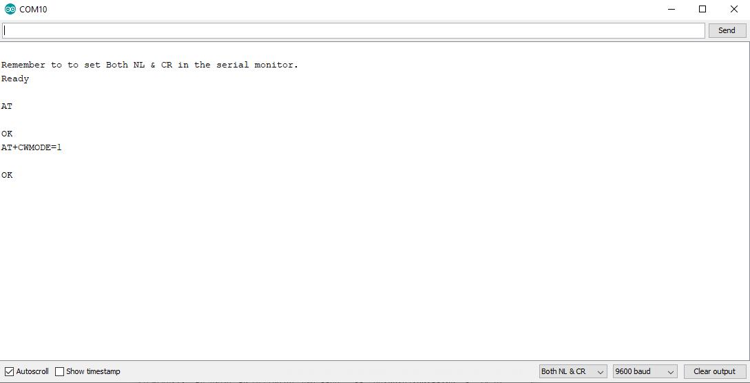
Step 2: Connecting to WiFi
Once communication is re-established at 9600 baud, test by sending AT again to confirm.
Then, set the operating mode to Station (Client) mode using the command:
AT+CWMODE=1
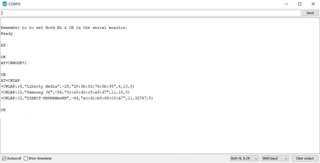
Step 3: Scanning for and Connecting to a Network
Try scanning for nearby WiFi networks with the command:
AT+CWLAP
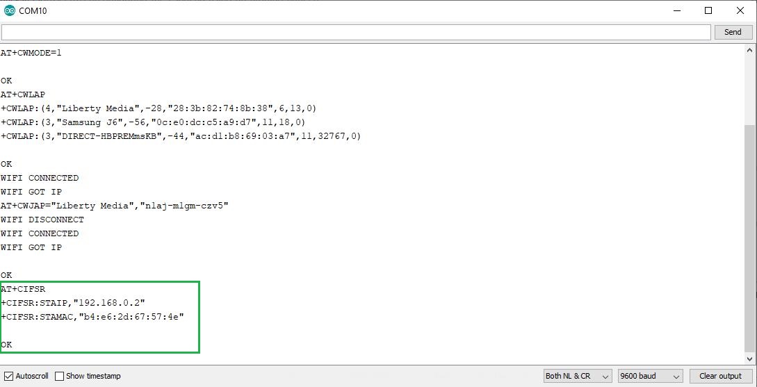
Once you find your WiFi name, connect using the command (replace with your WiFi name and password):
AT+CWJAP="Your WiFi Name", "Your Password"

If you see WIFI CONNECTED and WIFI GOT IP, congratulations! Your module is now connected to the internet.
Finally, check the module's IP Address using the command:
AT+CIFSR
Conclusion and Next Steps
Now you have an ESP8266 module that's ready to use and connected to the outside world. This is the first door to creating more complex IoT projects. In the next article, we will learn how to control a servo motor via a webpage using the ESP8266 and Arduino!
Follow for more cool projects at: virginrobotics.blogspot.com