I decided to design a binary clock using flip-disc displays. I use the Arduino platform very often and this time I did the same. The clock is basically a simplified and modified copy of the Arduino Uno (see the diagram and description below) and the code is written in the Arduino IDE.
The clock should display hours and minutes. I also thought about seconds but came to the conclusion that reading seconds in the binary system can introduce unnecessary confusion - decoding the value takes a while, of course you can learn to read it quickly but for an inexperienced user it can be inconvenient. Assuming that each disc is another bit, with 6 discs the largest value is 63, which is ideal for displaying seconds 0-59. The top row corresponding to the hours does not need as many bits but for the aesthetics of the clock it will have the same number of bits.
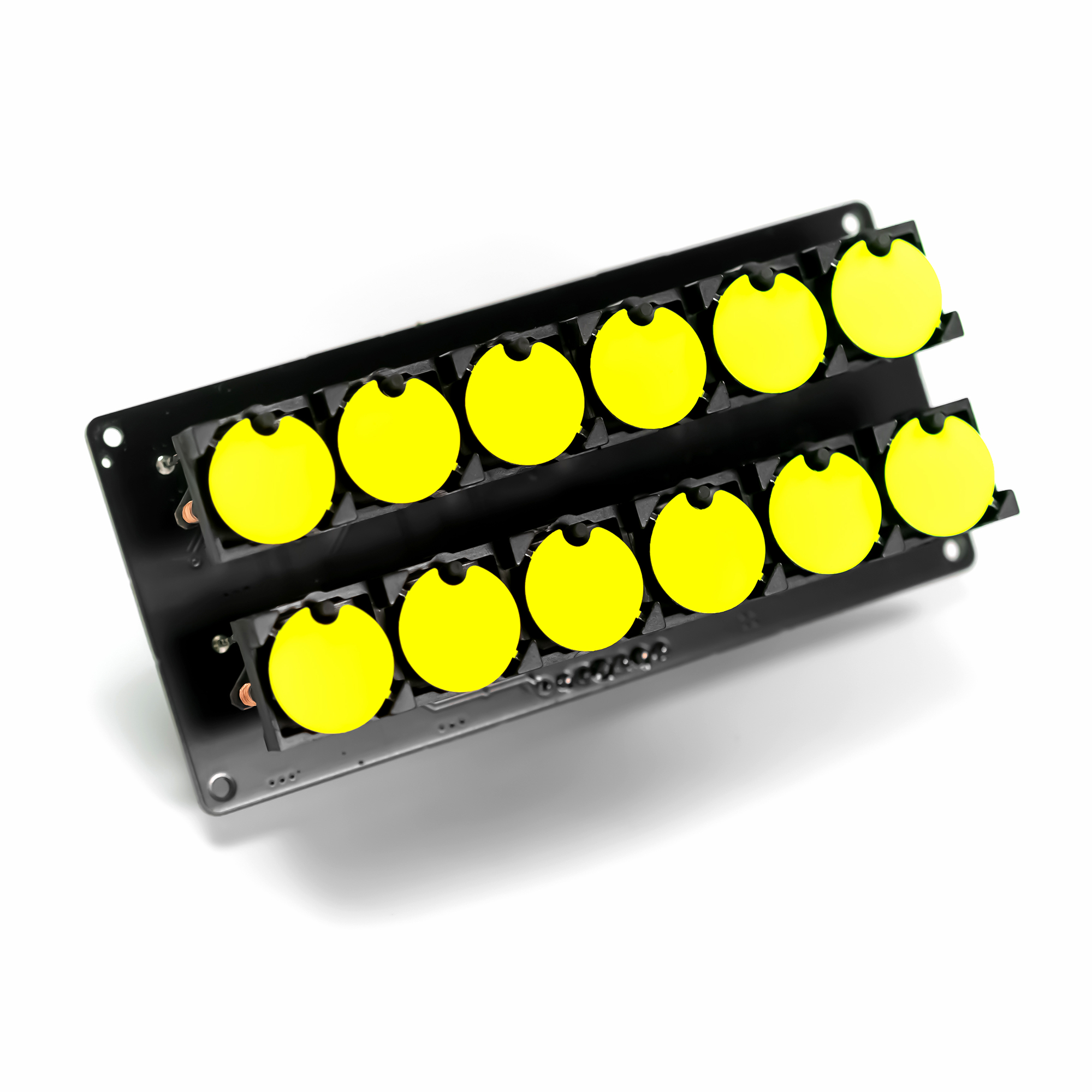
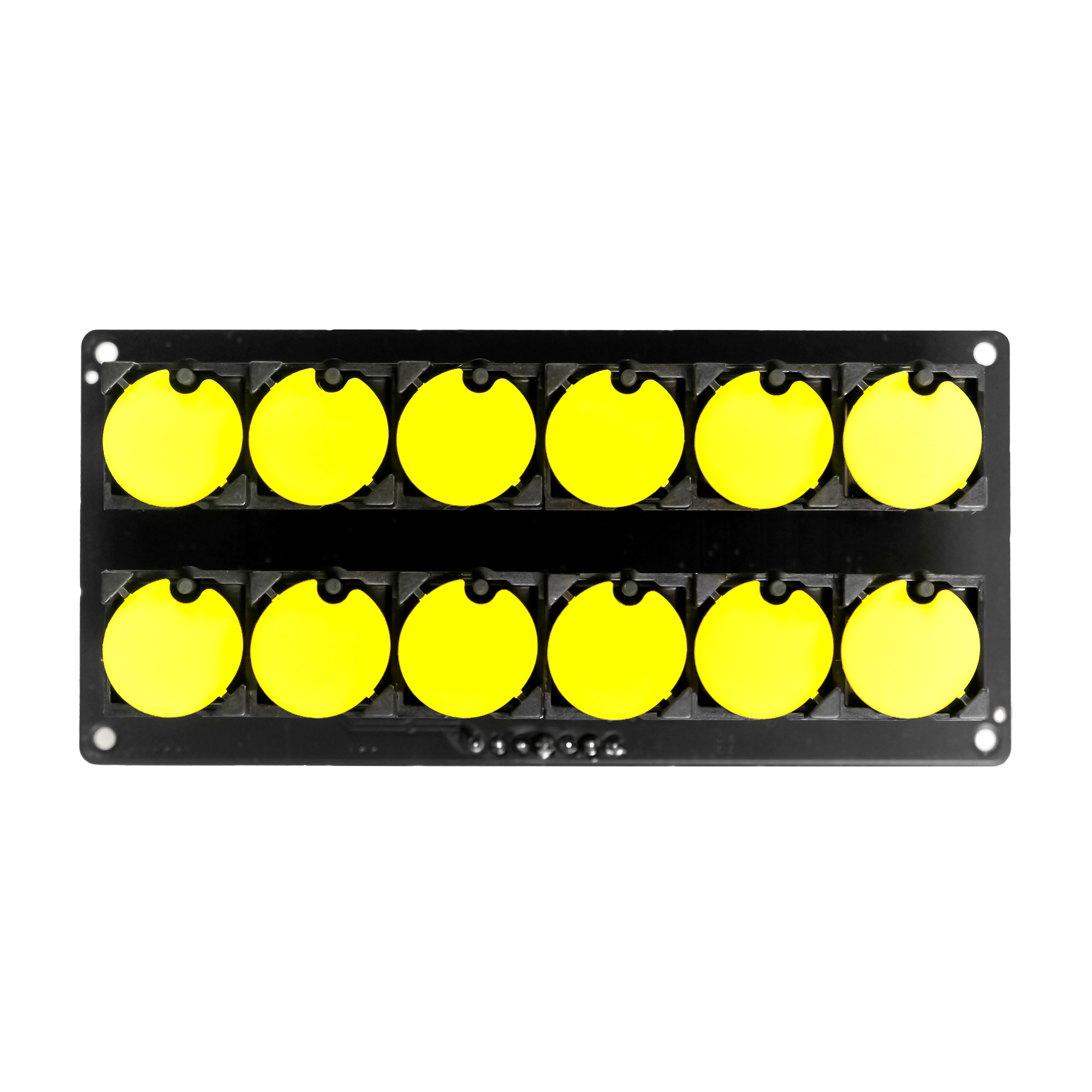
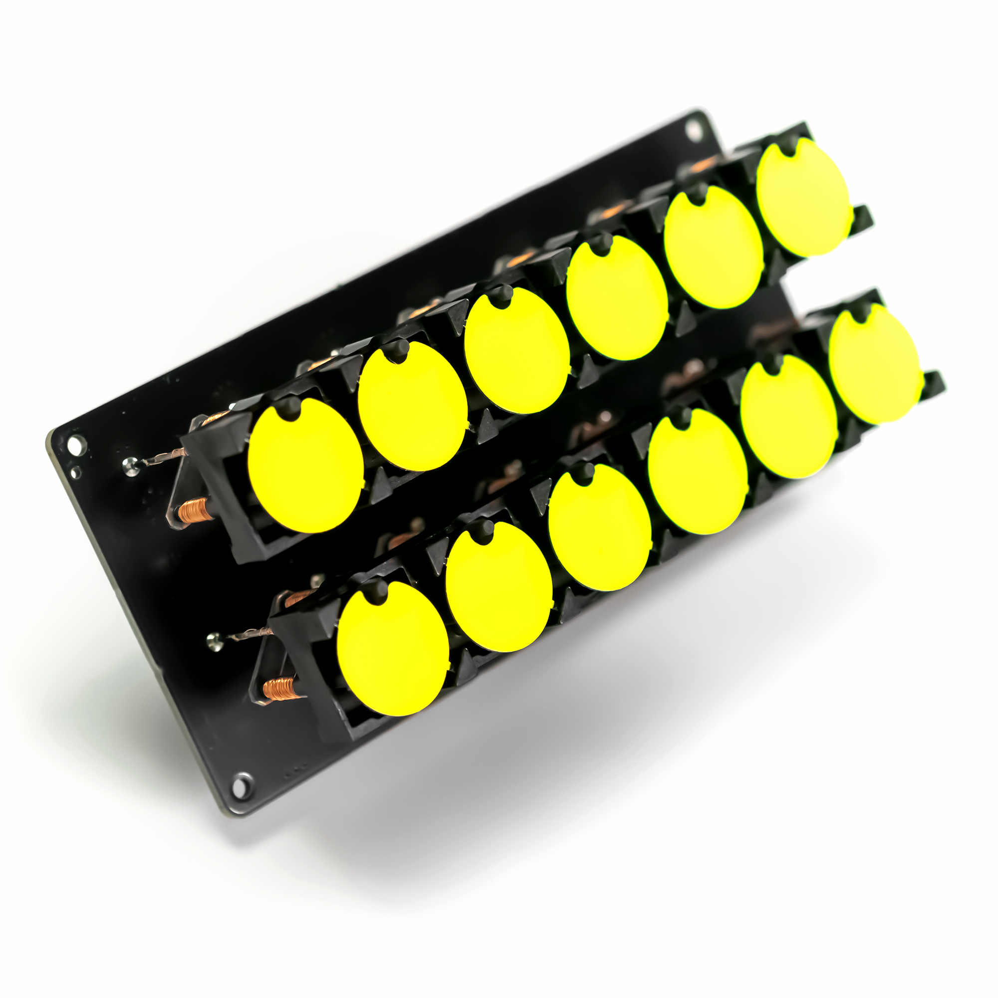
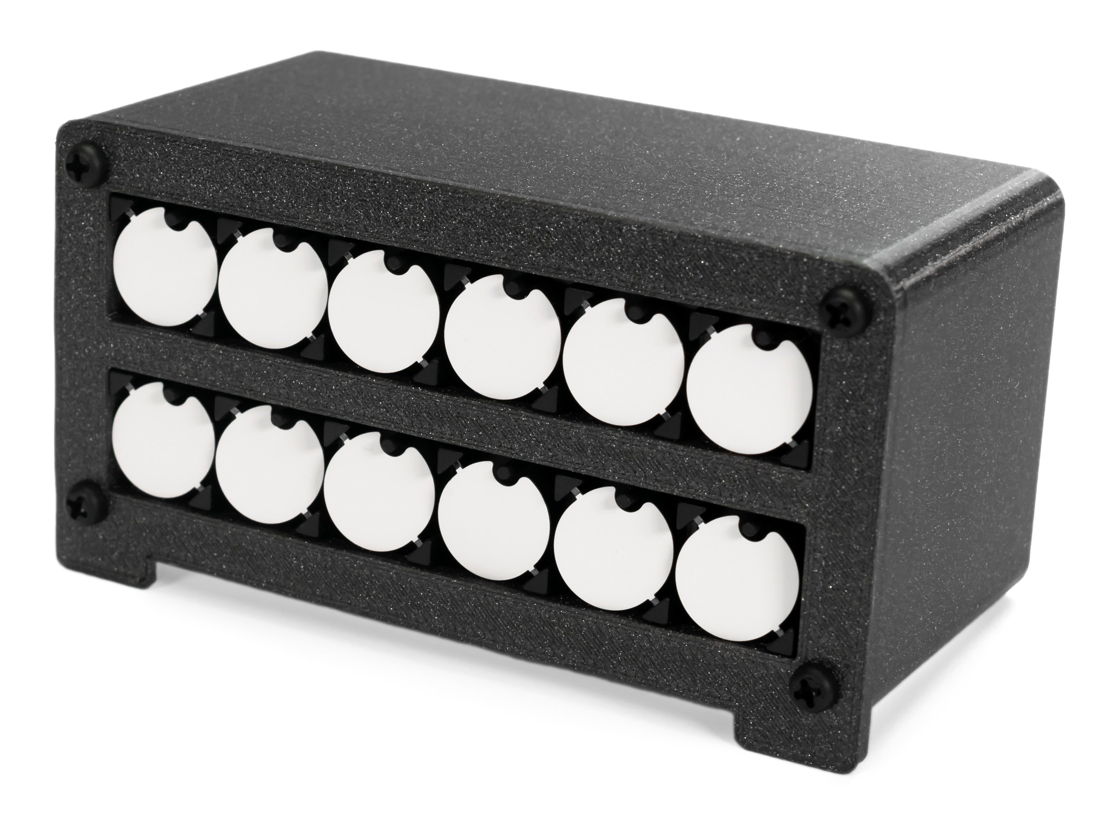
The top row for displaying hours and the bottom for minutes.
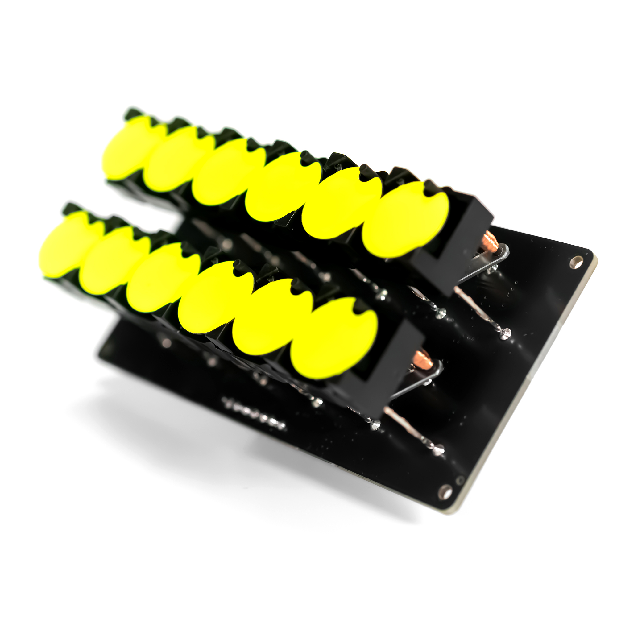
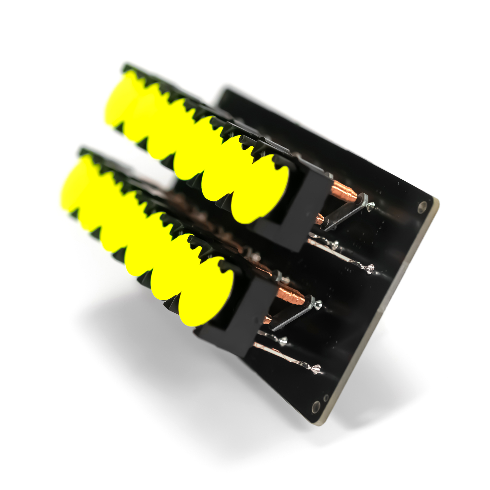
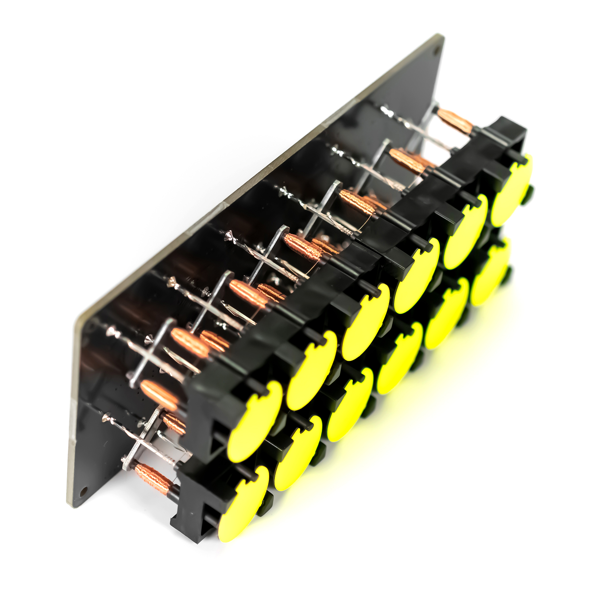
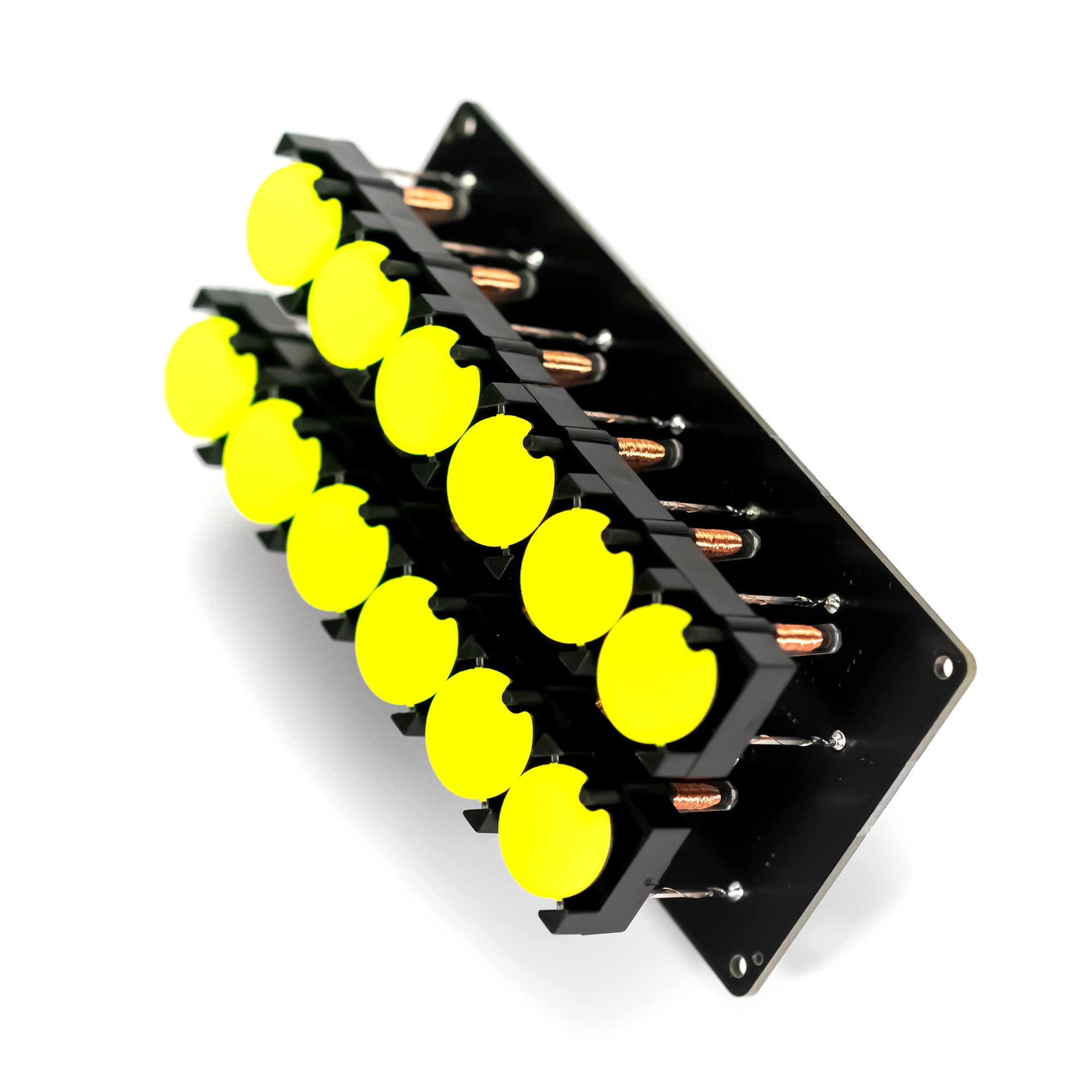
The **Flip-Disc Binary Clock** is an exercise in managing hundreds of individual magnetic actuators. Flip-discs (often seen on old bus destination signs) are electromechanical dots. One side is black, the other is bright yellow. By pulsing an electromagnet beneath them, the disc violently "flips," making an incredibly satisfying clicking sound.
Electromechanical Actuation
Flip-disc displays are really old technology, they are electromechanical displays. The control is very specific and is based on precise current pulses thanks to which we can rotate individual discs. A detailed explanation of how flip-disc displays work and how to control them can be found here
Flip discs do not use static electricity like an LED. They use magnetic polarity mapping.
- The Pulse: You must send a 24V pulse of electricity through the coil for exactly 1 millisecond.
- The Reversal: To flip the disc back to black, you must physically reverse the polarity of the current (using an H-Bridge).
Design assumptions:
- modular design
- displaying hours and minutes in binary code
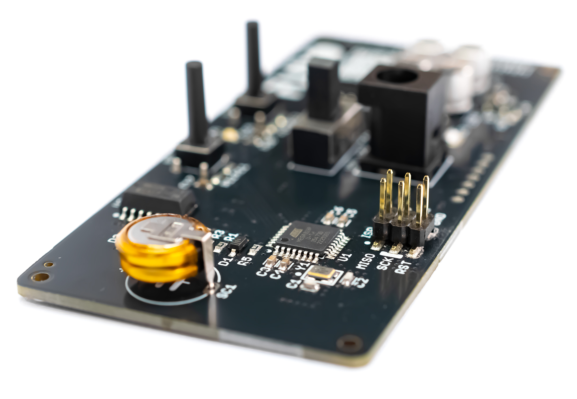
- ATmega328 as the heart of the clock
- clock code written in Arduino IDE
- option to update the clock code yourself
- accurate RTC real-time clock on board
- RTC backup power supply - supercapacitor
- time setting buttons
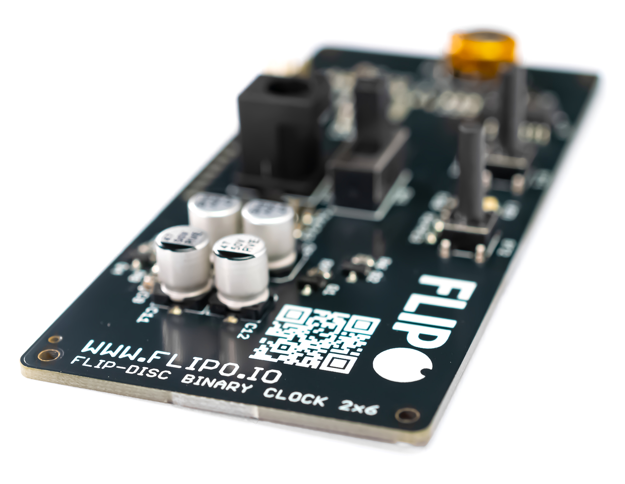
- clock power switch
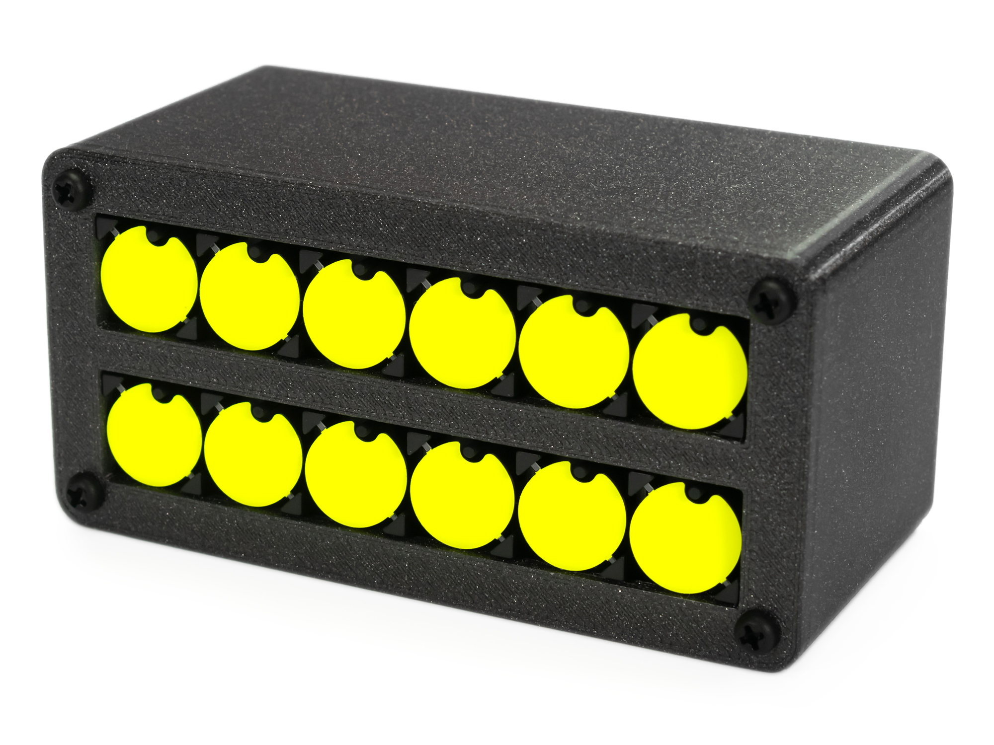
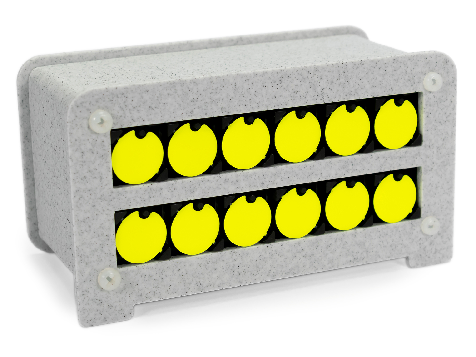
- simple, aesthetic casing for 3d printing and/or laser cutting
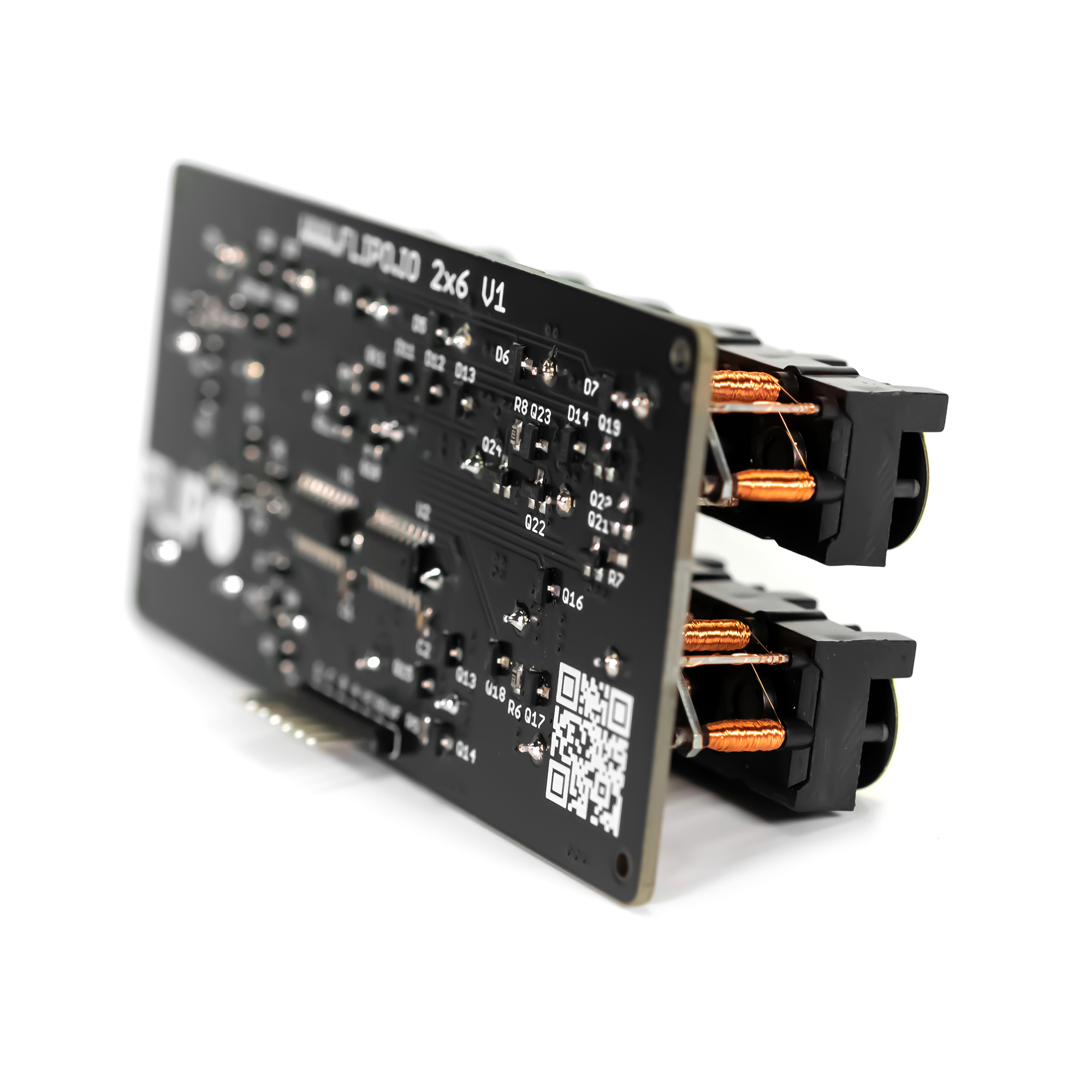
I like modular construction of electronic devices, so the clock will be a compact structure of two pcb boards connected to each other and to the casing with a set of spacers. The clock consists of two main modules: a 2x6 display module and a clock controller module.
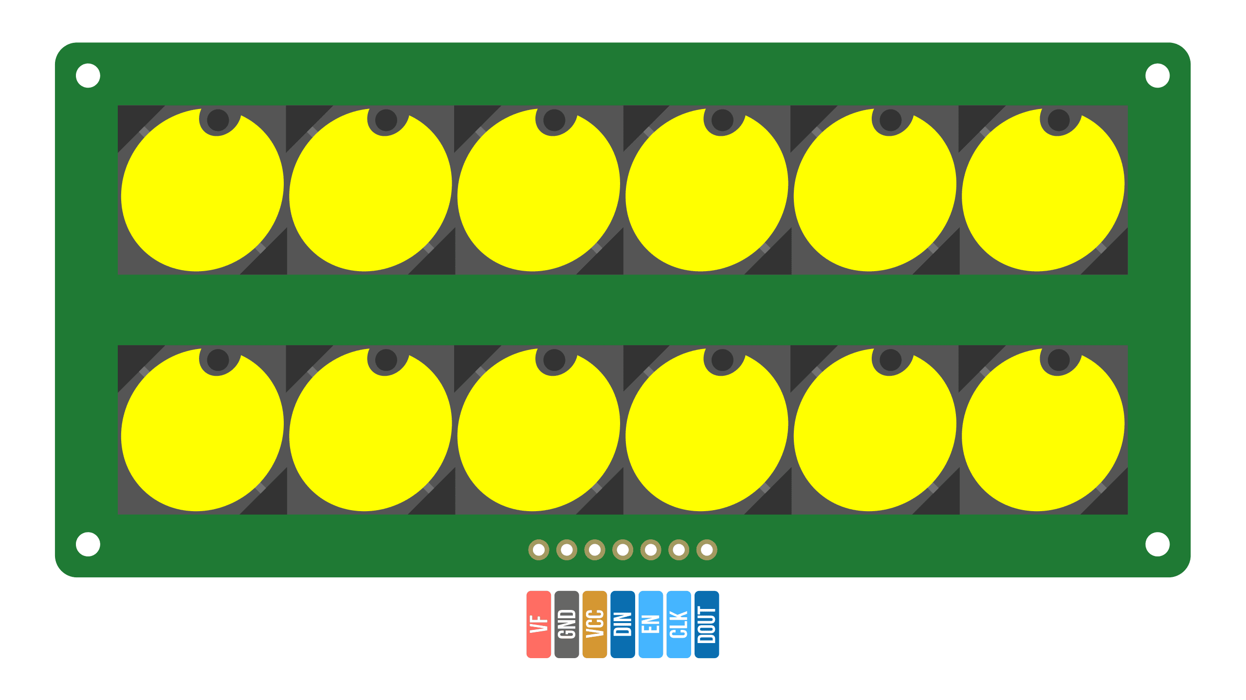
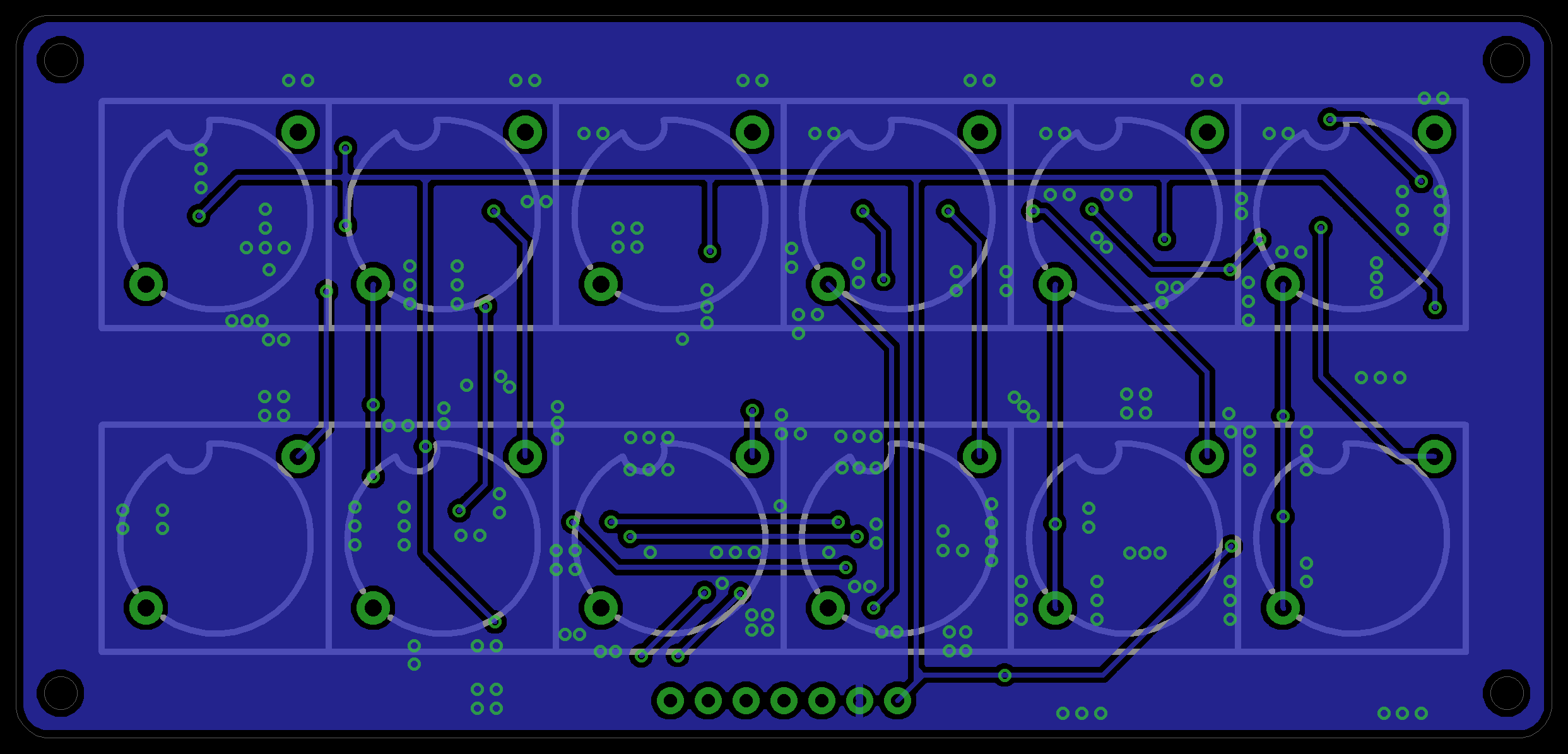
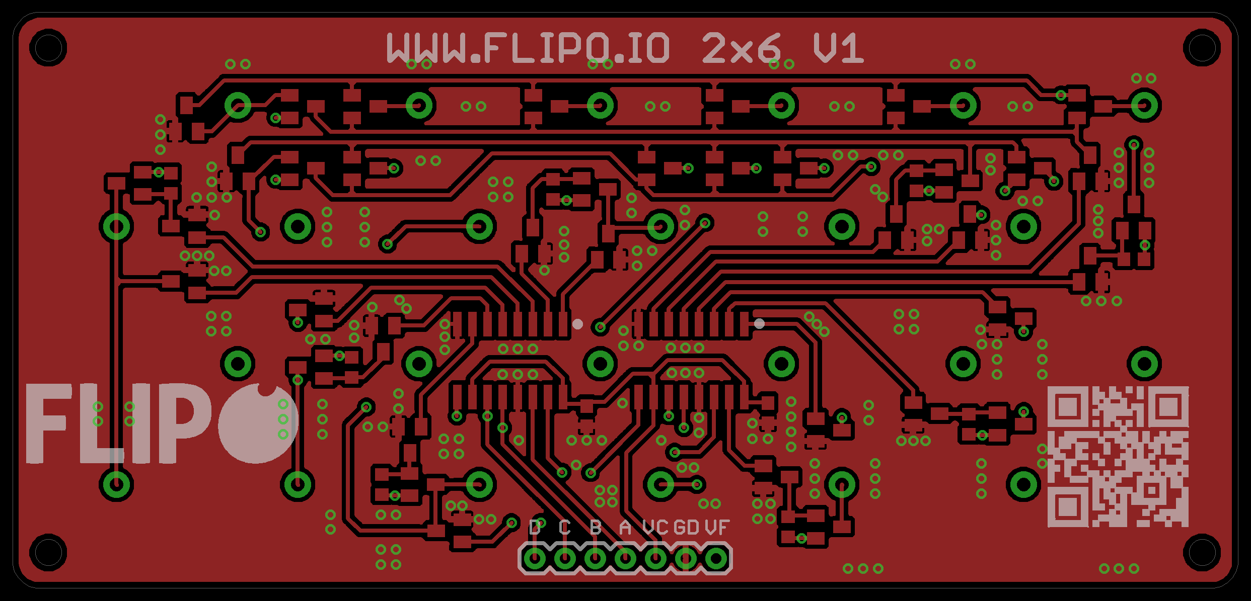
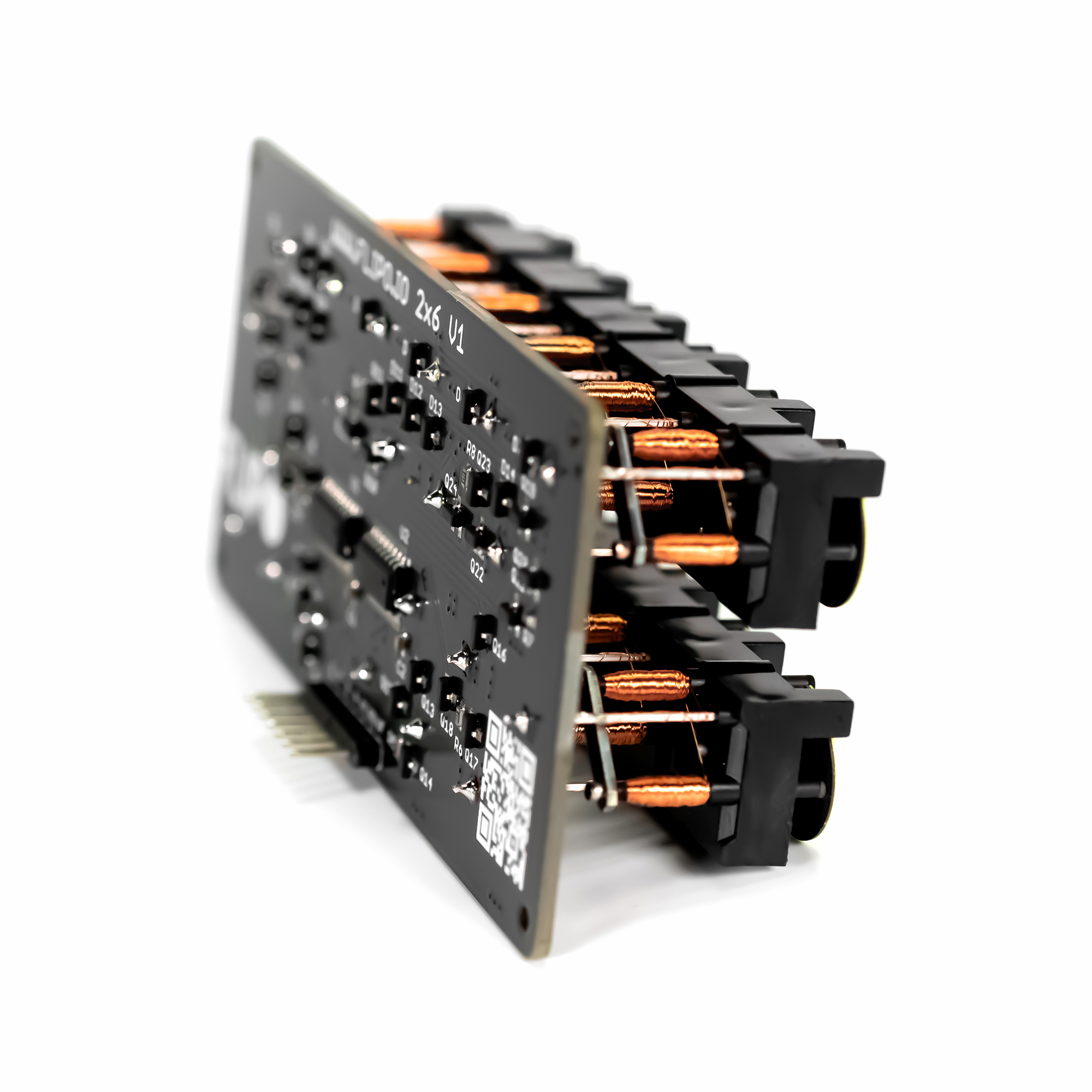
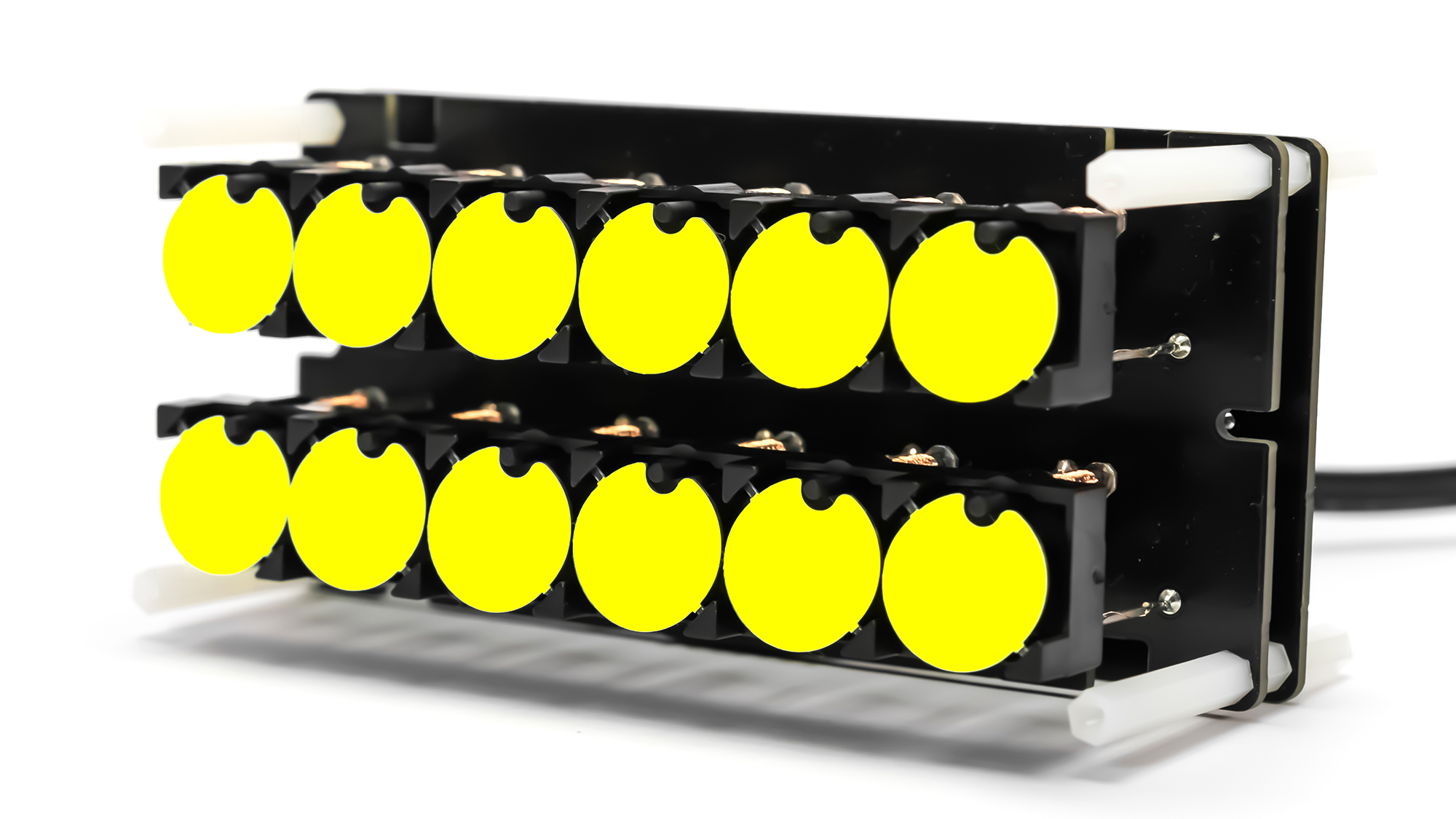
2x6 Flip-disc display
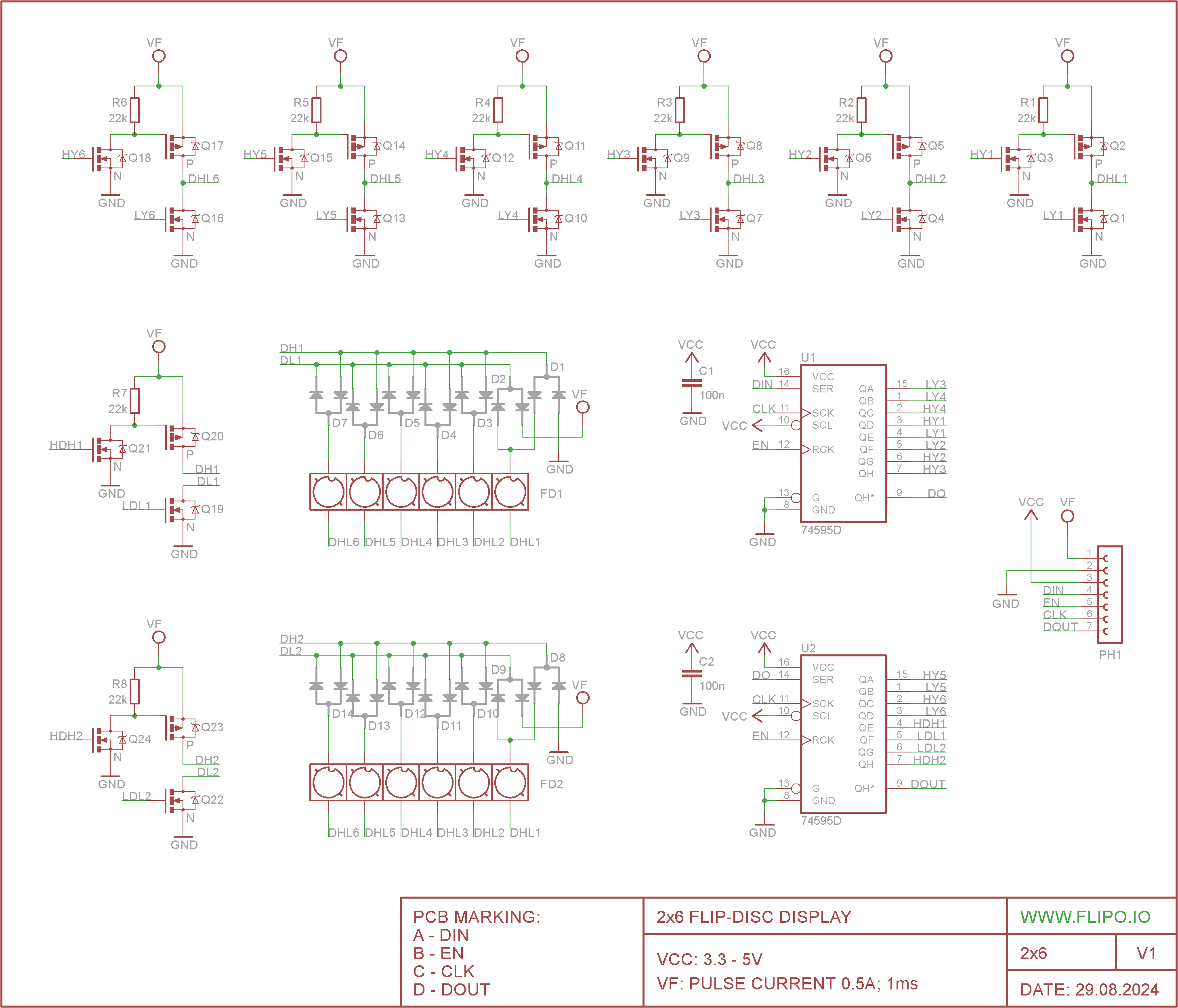
Display with two rows of 6 discs each. The simplest way to control flip-disc display is to control one disc at a time (see detailed explanation). With this assumption, we can treat both rows as a matrix of two rows and 6 columns, which will reduce by half the number of mosfet transistors needed to control individual discs. See the diagram below or download
The H-Bridge Matrix Array
You cannot attach an H-Bridge to 60 individual discs. You must use a Matrix Multiplexing strategy.
- You organize the coils into Rows and Columns.
- You use a massive array of Shift Registers (74HC595) and Darlington Transistor Arrays (ULN2803).
- To flip the disc at Column 3, Row 5: The Arduino throws Row 5 to HIGH voltage and sinks Column 3 to Ground for a split second. Then it turns everything off.
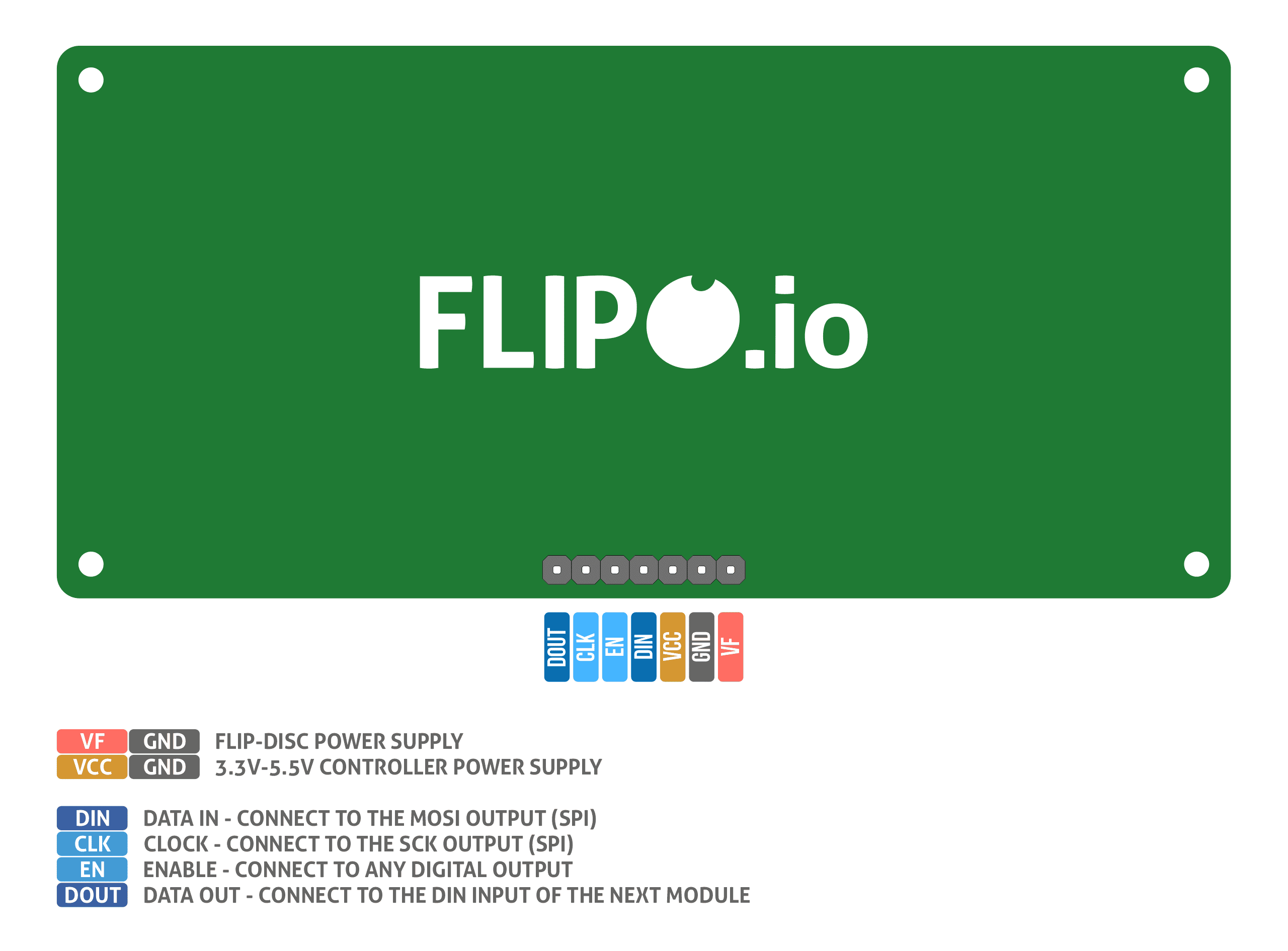
I used mosfet N/P transistors to directly control the discs, while the transistors are controlled by two popular 595D shift registers. This reduced the number of control lines used by the microcontroller to 3. You can, of course, omit the shift registers and control the transistors directly through the microcontroller using 16 pins but then only a few pins remain for other tasks. I also wanted the 2x6 flip-disc display to be versatile and usable for purposes other than the binary clock. There is another advantage of using shift registers that I didn't mention: the displays can be connected in series with each other up to 8 and all the time the number of control lines will remain the same - only 3 lines. Connecting flip-disc displays in series is made possible by a dedicated library for Arduino FlipDisc.h
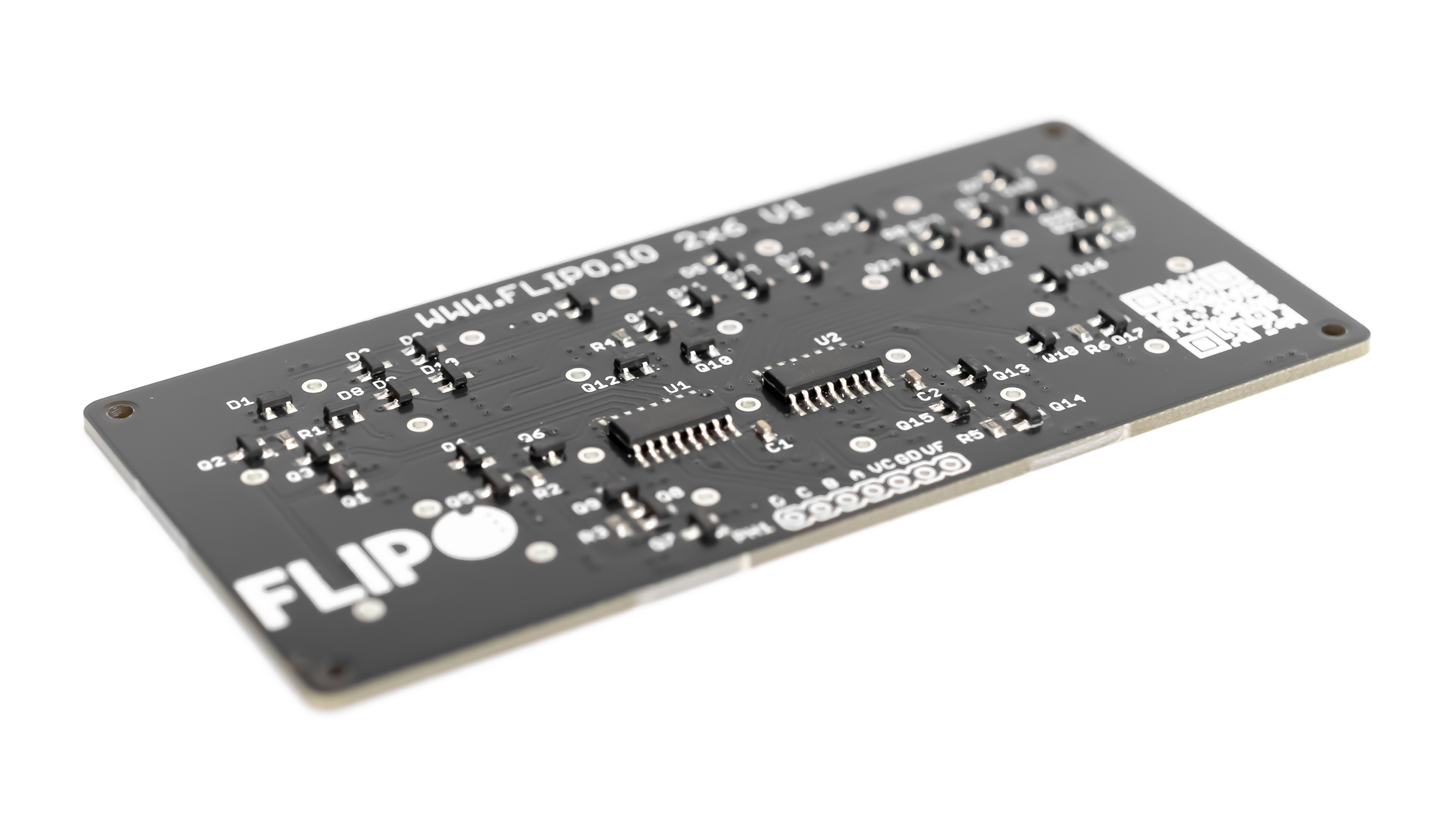
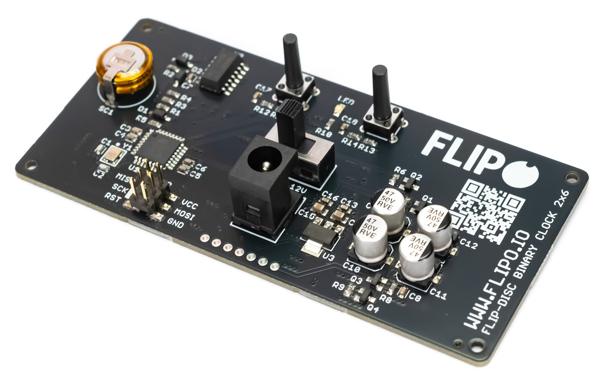
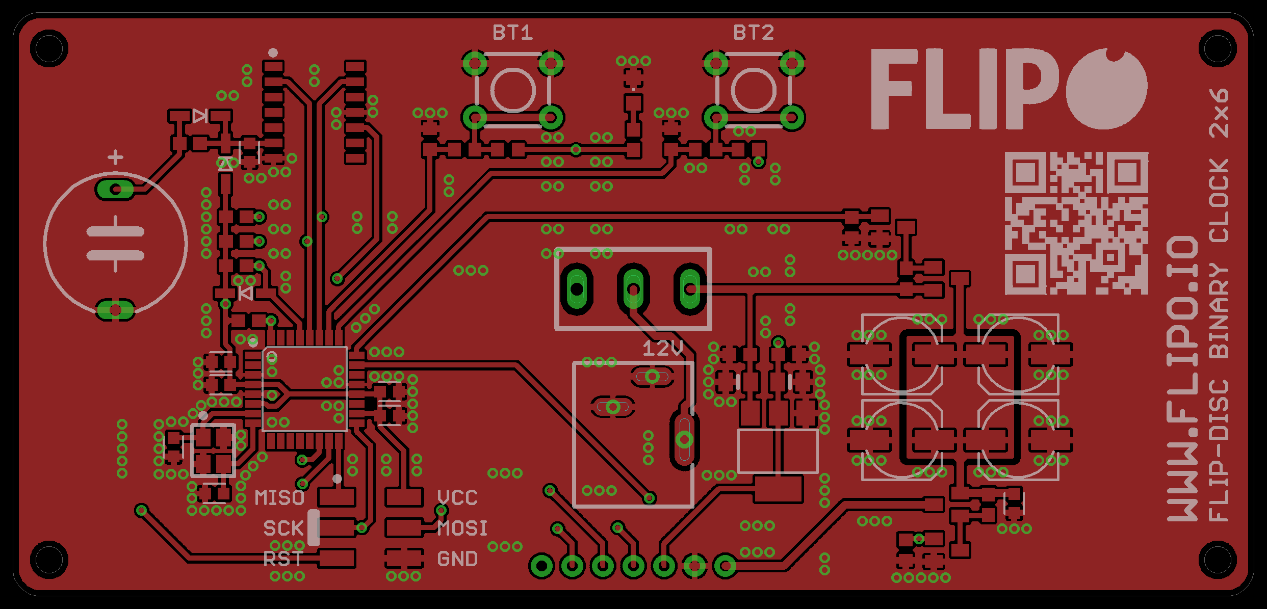
Binary Clock Controller
Below you will find a schematic of the clock controller - download schematic.
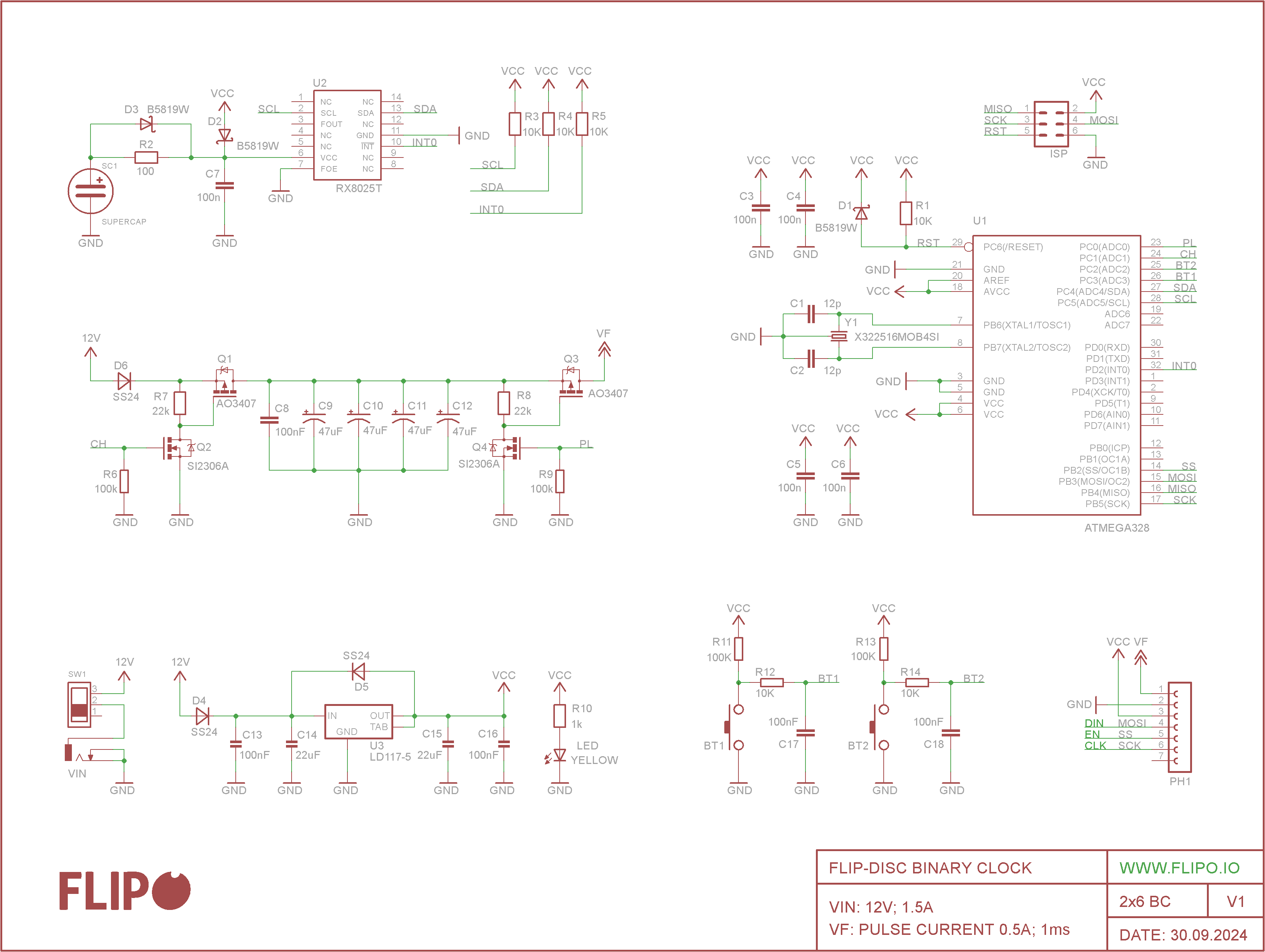
I chose the RX8025T real-time clock - I wrote the RX8025T.h library for Arduino. The accuracy of the clock is comparable to the popular DS3231.
How the binary clock works: The RX8025T stores the current time and generates an interrupt to the INT0 output every 60 seconds. The ATmega328, upon detecting the interrupt, reads the current time from the RTC and displays it on the flip-disc display in binary code. The RTC clock has a backup power supply, a supercapacitor. Two buttons are used to set the time and the 12/24 hour format. The clock's power supply is quite archaic as it is 12V - this was the easiest way without unnecessary DC-DC converters. The microcontroller and all control electronics operate on a 5V.
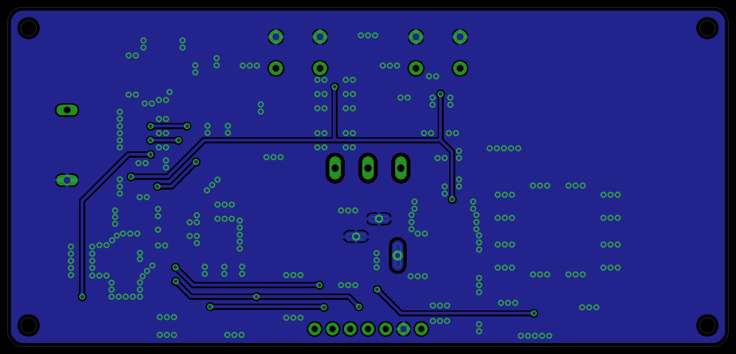
VF - power supply for flip-disc displays requires some more extensive explanation.
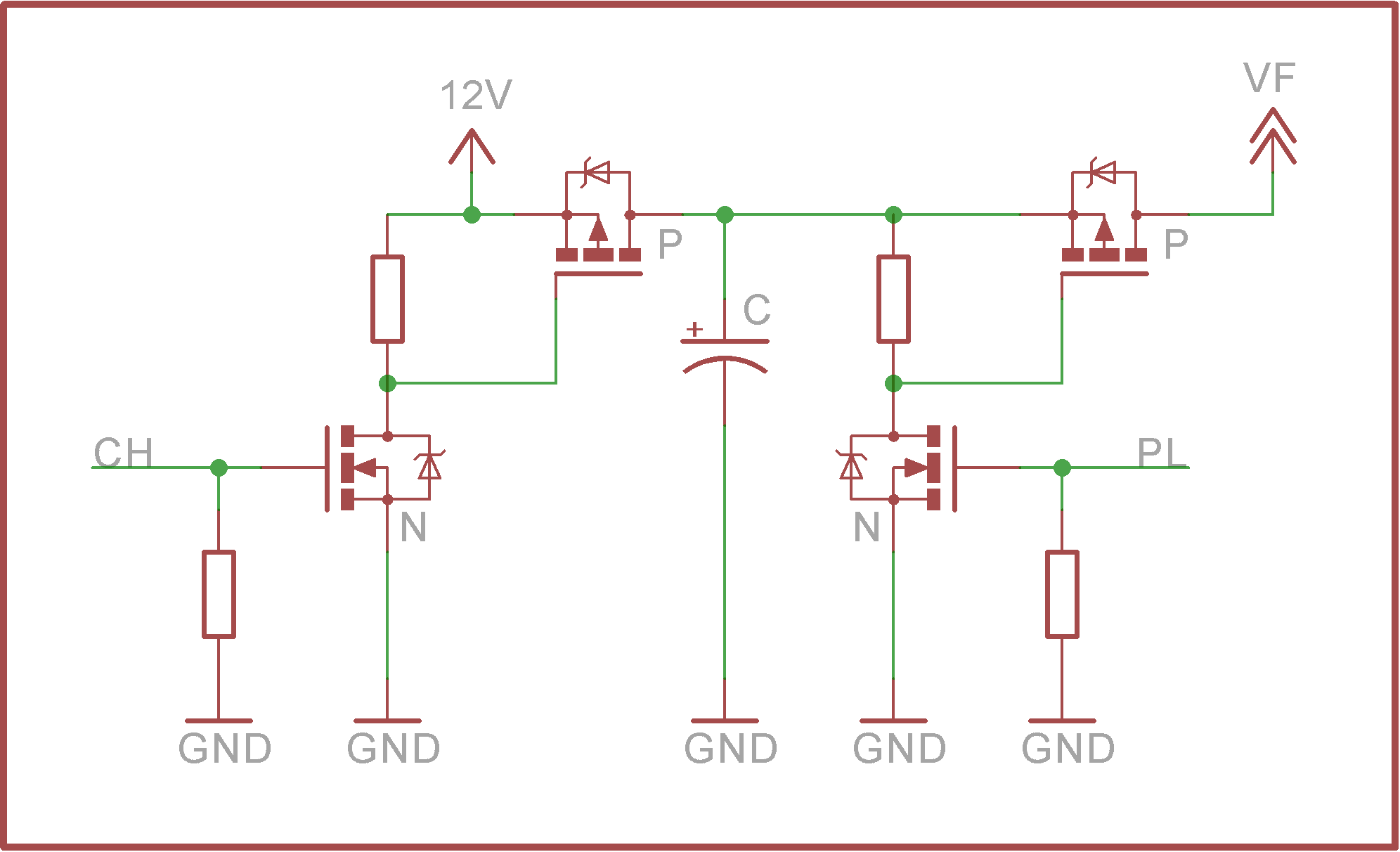
The pulse shaper power supply consists of two transistor switches and a capacitors. When the CH (charging) line is turned on, the capacitor accumulates charge, then the charge is released when the PL (pulse) line is turned on.
A more detailed description of the operation can be found here
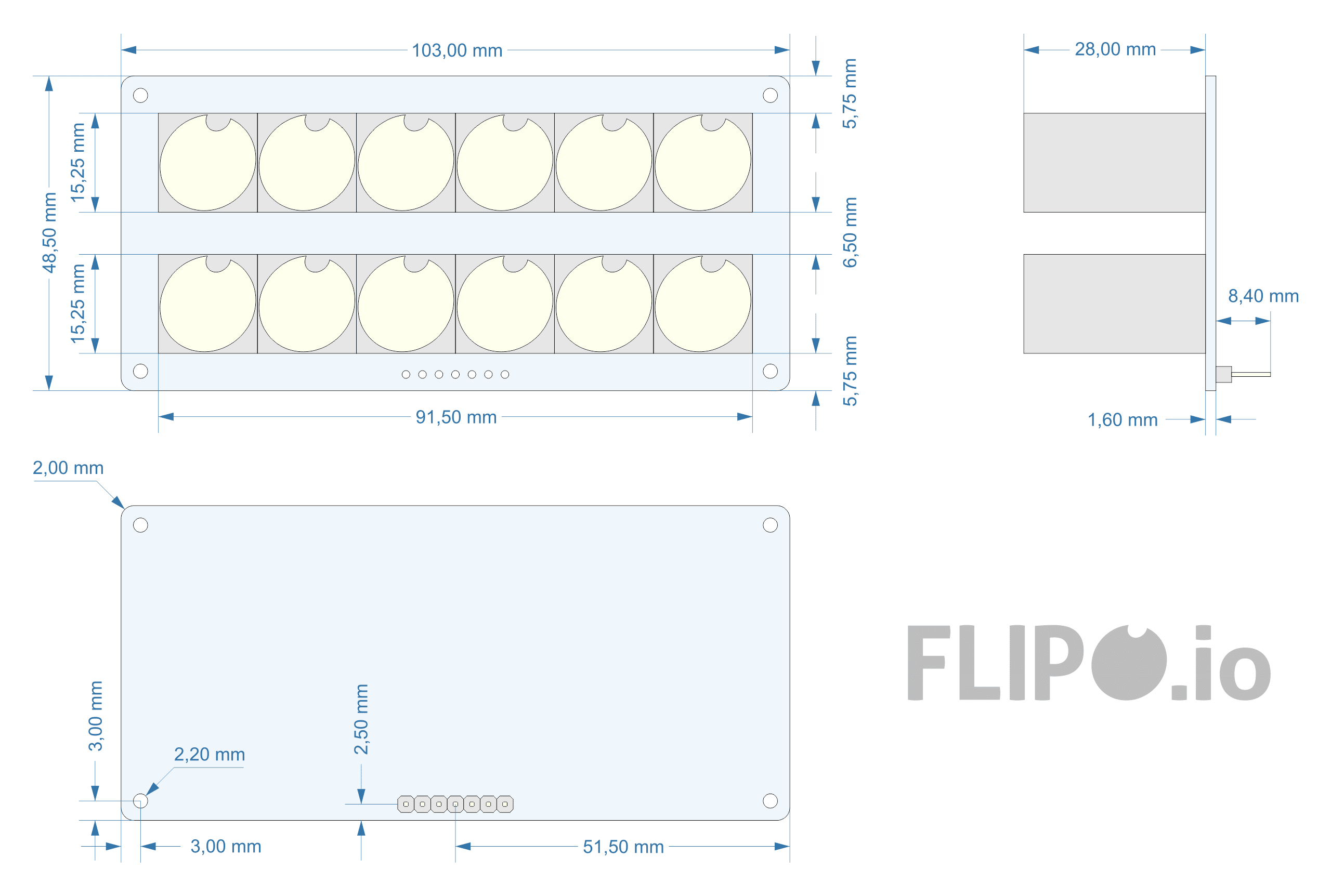
The controller board can be connected to the flip-disc display board via the PH1 pin connector on both boards. To further stiffen the structure, there are 4 spacers of 6mm length between the boards, the remaining spacers are used to screw the clock to the case.
How to Read Binary Time
The clock displays hours and minutes. The top row displaying hours and the bottom row displaying minutes. The time is displayed in binary code, i.e. each of the discs in the two rows has a different bit weight, starting from 2^0 = 1, each successive bit is another power of two 2^1 = 2, 2^2 = 4 etc. Inactive discs are ignored and have a binary representation of 0, while displayed discs are 1. Adding up the active discs, we can read the time.
It may not be easy at first and requires some mental effort, but it gives some intellectual satisfaction and you can quickly learn to read the binary code.
Telling the Time (Binary)
Instead of spelling out "12:30", the clock uses Binary (Base-2).
- The top row has 6 columns representing the numbers 32, 16, 8, 4, 2, 1.
- The bottom row has 6 columns representing the numbers 32, 16, 8, 4, 2, 1 for minutes.
- If the 8-disc and 1-disc are flipped yellow, the hour is 9!
Casing Design
- 3d printable #1 design - open
- 3d printable #2 design - open
- 3d printable #3 design - open
Arduino Code
The heart of the clock is the ATmega 328 microcontroller (default 16 MHz external crystal). The clock code was written in the Arduino IDE and uses MiniCore
If you