Overview
Many times it is necessary to produce a programmable frequency output or implement a frequency counter for various uses. This project implements either or both of these functional blocks using only a low cost (≈$5-$17) Pro Micro (Sparkfun DEV-12640 or equivalent clone) module with an ATMega32U4 processor chip and software implemented using the Arduino IDE compiler and environment. These functional blocks can be used separately or together in a larger application or as a stand alone device. Since they are independent functions they will be covered separately. As part of this project a common main module is also included that can be used to set up the frequency generator or read the frequency from the frequency counter. This may be done via a serial port or alternatively, with 4 push button switches and an LCD display to use these functions as a stand alone device.
Unlike many of the projects listed on this site, instead of implementing some final device, this project focuses on the functional blocks for a frequency generator and a frequency counter. It is assumed that the user will then write a main module that deploys these modules for whatever purpose is desired, and may include an LCD display, a keyboard or other external interface, or may be part of some larger project the user needs. Finally, because both the frequency generator and frequency counter depend on the Pro Micro’s normally uncalibrated internal crystal oscillator, details of how to modify the module to improve the accuracy of the oscillator is detailed.
It should be noted that other Arduino modules with the ATMega32U4 processor could also be used, including the Arduino Leonardo and Arduino Micro and possibly others.
Frequency Generator
This library implements a variable frequency generator using Timer 4 on an Arduino Pro Micro module (using an ATMega32U4). This signal may be used to output an adjustable frequency square wave signal to any user defined device or circuit. The frequency generator will output a square wave signal with a 50% duty cycle from 1 Hz to approximately 12MHz, using hardware contained within the Pro Micro module itself. It can be used while also using all other functions of the module. Timer 4 on this processor/module is unique in that it can be connected to the processors main clock or can be connected to the PLL contained in the ATMega32U4 providing higher initial frequencies and some additional scaling values including 1.5x clock, providing more combinations of count values to produce an output signal closer to any desired frequency. Several other ATMega/Tiny processors also have this type of timer, but they are not too common.
The firmware for setting the frequency contains a unique algorithm that sets the output frequency to the closest value to the requested frequency as is possible by selecting from one of three different input clock frequencies (via the on-chip PLL), a binary prescaler value and a count value. With all these variables, which settings for each to obtain a given frequency could be challenging if they had to be determined externally. With the algorithm contained in the firmware, the firmware itself determines the optimal value for each of these three values so that the output frequency is as close to the requested value as is possible. Once these values are calculated and set, the Pro Micro module will output the requested frequency with no further firmware/software involvement since it is using the timer/counter in an auto reload mode with no interrupts.
Generator Hardware
The Pro Micro module will output the selected frequency clock signal on Arduino Digital pin 5 (processor pin PC6) as a 0-5V 50% duty cycle square wave signal with no further modifications to the controller. Alternatively, the output can also be configured to output the signal on Arduino Digital pin 10 (processor pin PB6), if desired. The figure below shows the pin(s) for the frequency generator output on the Pro Micro module.
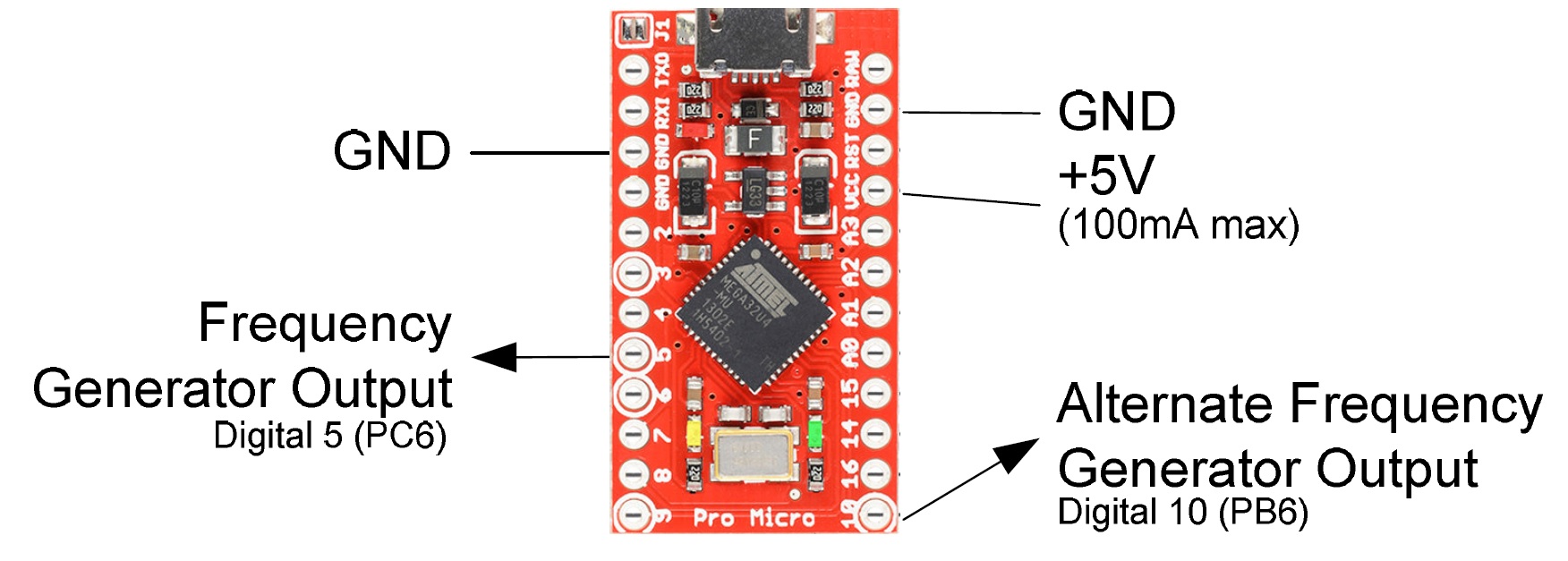
Depending on your application, no additional circuitry may be required, but if different levels or more power than the modules output pin can deliver is required, an external amplifier, level shifter or resistive divider may be needed. A 5V power source is also shown that can be used to power this external circuitry if needed and its power requirements are less than 100mA.
The frequency accuracy of this generator is directly related to the crystal oscillator on the Pro Micro module and is usually within 0.1-0.2%, but is typically closer than this to the nominal frequency. See the section below that details modifications to the Pro Micros crystal oscillator if greater accuracy is needed. Frequency accuracy is also related to the values that are set in the various registers of the processor chip. While the algorithm tries to determine the best values for the PLL, prescaler and counter, there are frequencies that are unobtainable with the hardware, without additional software intervention, which is beyond the scope of this project. Almost all lower frequencies (below about 5KHz) are perfect (or nearly perfect), meaning the module can output the exact frequency, but as the requested frequency goes higher, there will be ‘gaps’ where the exact frequency is not achievable. In these cases the closest frequency obtainable will be set and is usually close enough for most applications. The duty cycle of the output is fixed at 50%.
Generator Software Interface Functions
The library is implemented in a single class named “FrequencyGenerator”. This class has two functions: “set” and “read” to set the frequency generator and read the current frequency that the generator is set to.
** Set Function **
The frequency is set with a frequency set command, which sets the frequency to the closest obtainable value. The function ‘FrequencyGenerator::set’ accepts a long integer that is the frequency to output in Hz. This may range from a value less than 0 (return current frequency) to 0 (generator off) to a value some over 1/2 the clock frequency of the micro (8MHz). With the stock Pro Micro modules available, it has been observed to work to about 12MHz. The ‘FrequencyGenerator::set’ function returns the set frequency if the frequency requested was set or -1 if unable to set to the desired frequency. Since the timer is set up to automatically reload, no interrupts or other software overhead is required — Just call the function and then the hardware will produce the output frequency with no additional intervention.
To turn off the frequency generator, simply call the ‘FrequencyGenerator::set’ function with a frequency of zero. This will disable the frequency generator and put its output pin in a high impedance state. The current frequency can also be requested by calling the ‘FrequencyGenerator::set’ function with -1 (or any negative number).
** Read Function **
A function ‘FrequencyGenerator::read’ is also provided to request the current frequency of the frequency generator module. The value returned will be the actual frequency that the controller is outputting (and the closest value the hardware is capable of outputting) and may be slightly different than the last set frequency. This is returned as a long integer.
Generator Code Details and Options
The frequency generator functionality is contained in the file “FrequencyGenerator.cpp”. The header file that contains the class prototype is in the file “FrequencyGenerator.h”. This module was specifically written for Timer 4 of the ATMega32U4 on a Pro Micro device (or other microcontroller devices with similar functional blocks) assuming the controller is running as a USB device with the PLL set at 96MHz and a crystal of 16MHz (This is the default for the Pro Micro device). It could possibly be reworked for other timers, but the resolution would be less.
The code in the “FrequencyGenerator.cpp” module contains the algorithm to set the various registers in the processor to the best values for the input frequency desired. It does so by successively doing the calculations for each PLL setting and then determining which PLL setting provides the closest output frequency to the desired value. The prescaler and count value are determined by calculating the log2 of the desired frequency and then converting these to a prescaler and count values for the registers. Once the best combination is determined the physical registers are set to these values. Comments in the code detail this algorithm in more detail.
Within the FrequencyGenerator.cpp module there are 2 conditional compilation defines that can either be defined or not. One of them is ‘FRQGENUSEPB6’ which, if defined to non-zero, will use Arduino Digital pin 10 (processor pin PB6) for output of the generator, instead of the default Arduino Digital pin 5 (processor pin PC6). The other define is ‘FRQGENDEBUG’, which, if defined to non-zero, will output some of the variables values to the serial port when setting the frequency for debug purposes.
Frequency Counter
This library implements a frequency counter using hardware timer/counter resources that are part of the Pro Micro module. It uses Timer 0 and another timer as a “gate” timer on the Pro Micro module. It works either as a traditional frequency counter by counting the number of pulses that occur on an input pin for a fixed amount of time (the gate time) or alternatively as a period counter where the time of a single or multiple cycles of the input waveform are measured. The traditional frequency counting mode is best when measuring faster signals while the period measuring mode provides more sub Hertz resolution when measuring lower frequency signals. The interface to this module is via 2 to 3 main functions. The first function provides the frequency read to the user, while a second function sets the frequency counter to either the traditional counting mode or the period measure mode and also sets either the gate time or the number of input pulses to average. Another function is available, if desired, to determine if a new “fresh” reading is available. Since this module uses hardware timers and interrupt routines to implement the frequency counter, it can be used while also using all other functions of the Pro Micro module and the Arduino environment in addition to whatever user written code is desired.
When the counter is configured in the traditional counting mode, Timer 0 is configured to count input pulses and a second timer (Timer 1) is used as the gating source. When counting, every time Timer 0 overflows, an interrupt routine adds one to a saved count variable. The gating timer (Timer 1) is used to periodically move this accumulated count to another variable that will then be returned to the user when the frequency is requested, and then resets the count in the Timer 0 counter (and it’s saved count variable) for the next cycle. The gating timer can be configured to one of 10 mS, 100 mS, 1 Second, 10 Seconds or 100 Seconds. The gating timer is also interrupt driven, so that the counter module can accurately time the gating window. There is also an external gating mode where a level on an external pin can be used to “gate” the frequency counter.
When the counter is in the period measuring mode, Timer 0 is used to count either a single transition or multiple transitions on the input pin. The system microseconds count (that is part of the Arduino environment) is saved upon the receipt of the first transition, and then when the second transition occurs, the microseconds value is again read and the saved microseconds value is subtracted from it to determine the period of the input signal. Then when the user requests the frequency, this value is converted to a frequency and returned to the user. In the period measuring mode, one of three averaging modes is available. Either no averaging or an average of 10 or 100 input pulses is selectable. This averaging is done by setting the Timer 0 counter to generate an interrupt on either 1, 10 or 100 transitions, effectively averaging the input signal.
Counter Hardware
Input to the frequency counter is on Arduino Digital pin 6 (processor pin PD7) for Pro Micro (ATMega32U4) and is assumed to be a low going train of pulses to count. The figure below shows the counter input and also the external gate input pin (detailed later). The external gate input, if used, is on Arduino Digital pin 9 (processor pin PB5), but can be moved to another pin if desired.
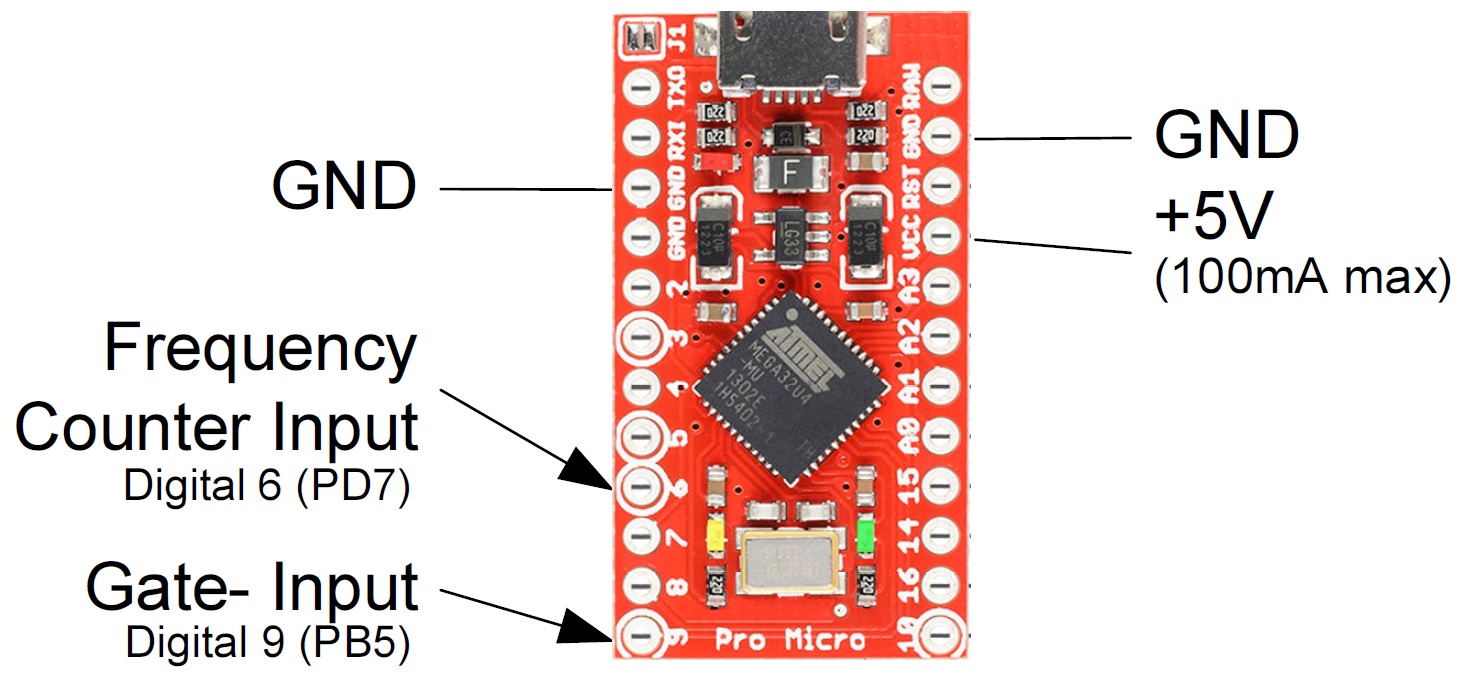
Obviously the input signal must be an appropriate TTL level to be counted. Input amplifiers to amplify a lower level signal to this TTL level (if needed) are beyond the scope of this work. A 5V power source is also shown that can be used to power any external circuitry if needed and its power requirements are less than 100mA.
The frequency accuracy of this counter is directly related to the crystal oscillator on the Pro Micro module and is usually within 0.1-0.2%, but is typically closer than this to the actual frequency. See the section below that details modifications to the Pro Micros crystal oscillator if greater accuracy is needed.
The accuracy is also directly related to the accuracy of the gate timer for the traditional frequency counter mode and the milliseconds timer for the period measuring mode. Both of these timers are interrupt driven in this project, meaning that they occur autonomously without any software intervention and occur as close to immediately as is possible in the Arduino environment. While there is some overhead for the interrupt routine, this is usually negligible and the frequencies read are typically very close to or normally exactly the correct frequency.
Testing on different modules that were available during development of this project revealed that in the traditional frequency counter mode, the Pro Micro module was able to reliably count frequencies up to about 8MHz (1/2 of the processor clock frequency). In the period measure mode, which is intended for measuring lower frequencies with more resolution, frequencies up to 20 KHz were possible and reliable when the averaging setting is 10 and 100 and 10 KHz when the averaging was turned off (average of 1). In the period measure mode, if the frequency is above these values, the module will either report a value of ‘999999’ or in some rare cases an erroneous value.
If the application requires measuring frequencies higher than about 8 MHz, then an external divider chain (prescaler) can be added to the input signal prior to connecting it to this counter module and then adjusting the values returned by this module accordingly. A 74196 or a collection of 74F74’s can be used for frequencies up to about 60-100MHz and other prescaler IC’s can be used for even higher frequencies. If a prescaler is used then a define named ‘FCPRESCALER’ in the “FrequencyCounter.cpp” module can be adjusted to the divisor value so that the output frequency returned is correct with the prescaler being used.
Counter Software Interface Functions
The library is implemented in a single class named “FrequencyCounter. This class has two main functions and a couple of ancillary functions that may be needed, depending on the exact implementation chosen.
** Mode Function **
The first function, ‘FrequencyCounter::mode’, is used to set or read the counting mode, which includes the mode and either the gate time or the number of averages. This is called with a single parameter that specifies the mode to use, or requests the current mode. If the input parameter is -1 (or any value less than 0), then the function returns the current mode value. If the input parameter is in the range of 0 to 9 the following mode is set:
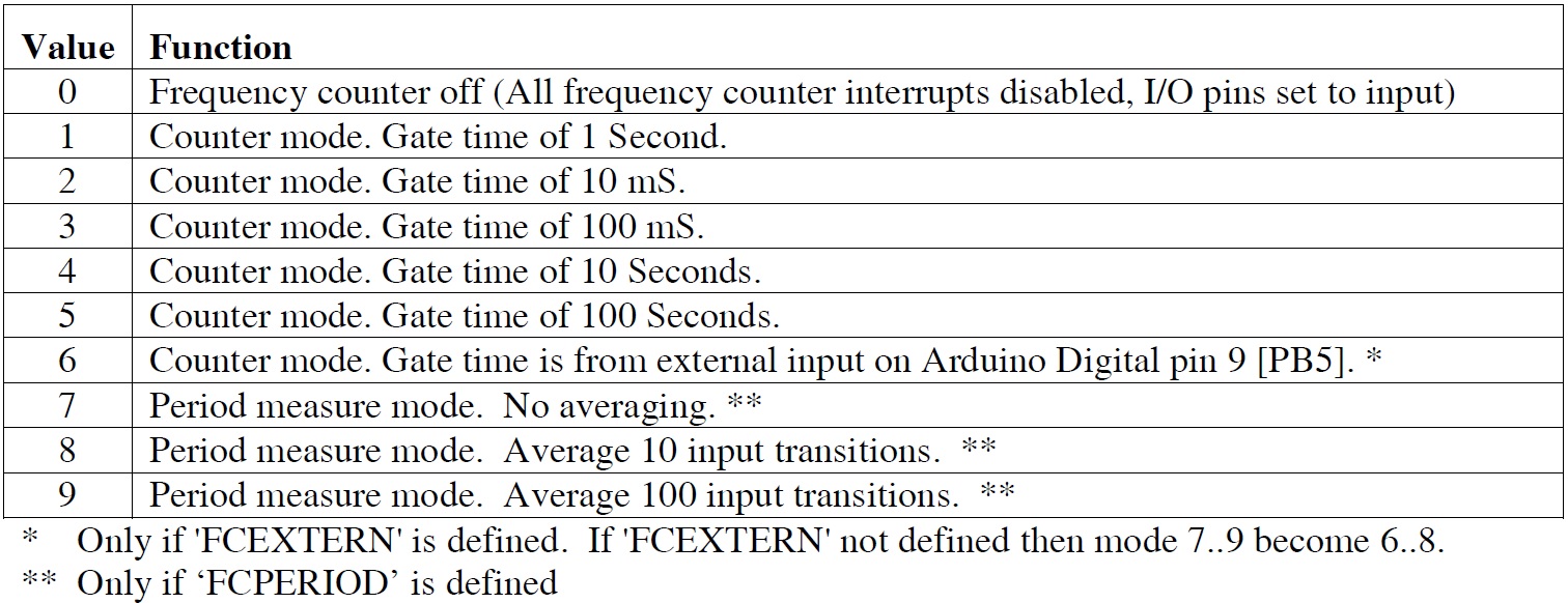
The function always returns the current mode selected or -1 if the input parameter is outside the range of the values mentioned above. Modes 6 thru 9 may or may not exist, depending on how the module is compiled. If the ‘FrequencyCounter::mode’ function is called without a parameter, it will return the current mode.
** Read Function **
The second function, ‘FrequencyCounter::read’, is used to read the frequency counter and return a string that is a numeric floating point value of the frequency read. This function is called with a pointer to a string buffer that will be filled in by this function and a parameter called ‘Wait’, that if non-zero will cause the function to wait until a new “fresh” reading of the frequency counter is available. The function returns a pointer to a string that contains this frequency value and is of the form “12345678” or “12345.67890” (or similar). The string buffer location passed to this function must be large enough to hold the string that this function will create – 15 or more characters is suggested. The parameter ‘Wait’ should be zero to get the last frequency read or non-zero to wait for a new “fresh” frequency count. It should be noted that if the function is called with the ‘Wait’ parameter as a non-zero value, the function may take up to 100 seconds to return, depending on the mode the frequency counter module is in. If this is unacceptable, a polling function is also available to see if a new frequency reading is available. This function returns a string that can be a floating point value instead of an actual binary floating point value type so that the compiler’s floating point functions (that consume a lot of code space) are not required.
** Available Function **
As mentioned in the last paragraph, a function to determine if a new “fresh” frequency reading is available is also included. The function ‘‘FrequencyCounter::available’’ requires no parameters and returns a 1 if a new value is ready and 0 if a new value is not ready.
Most users will only need the two or three functions mentioned above. In special circumstances, a couple of other functions are available.
** Read Binary Function **
When the function ‘‘FrequencyCounter::read’’ is called with only a “Wait” parameter (and no pointer to a string parameter) the read function returns a long integer that is the uncorrected count or period of the frequency read. The user would then have to scale / convert this to the proper value for the needs of the application. Like the string version of ‘‘FrequencyCounter::read’’ function this function also accepts a ‘Wait’ parameter