Introduction
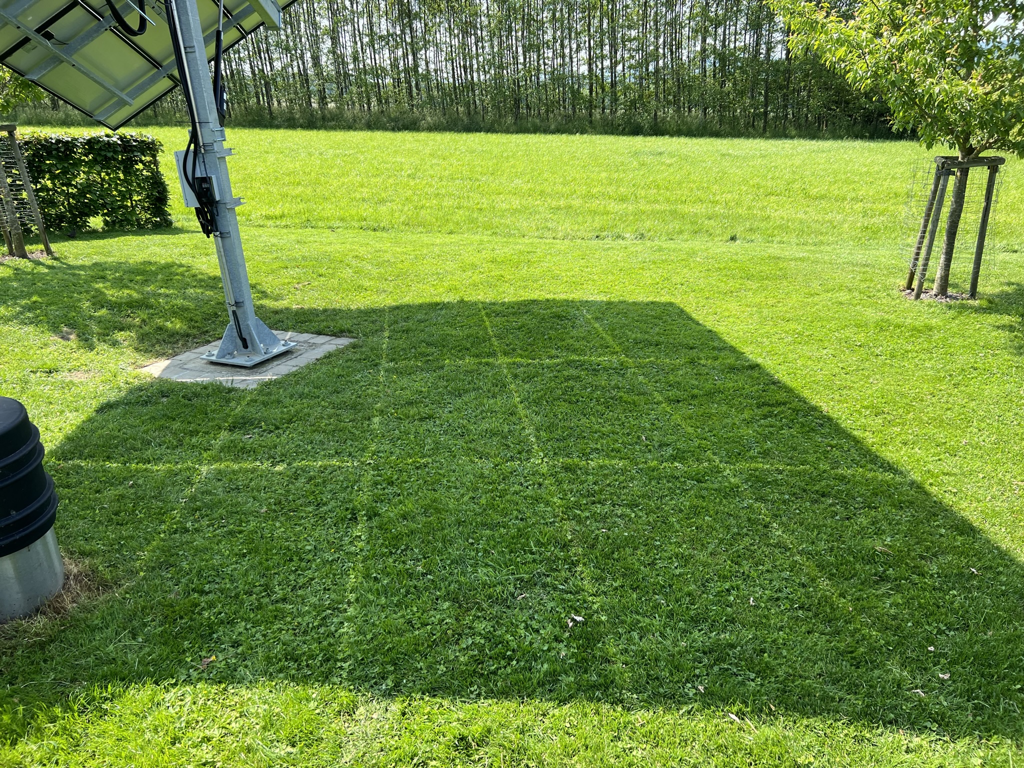
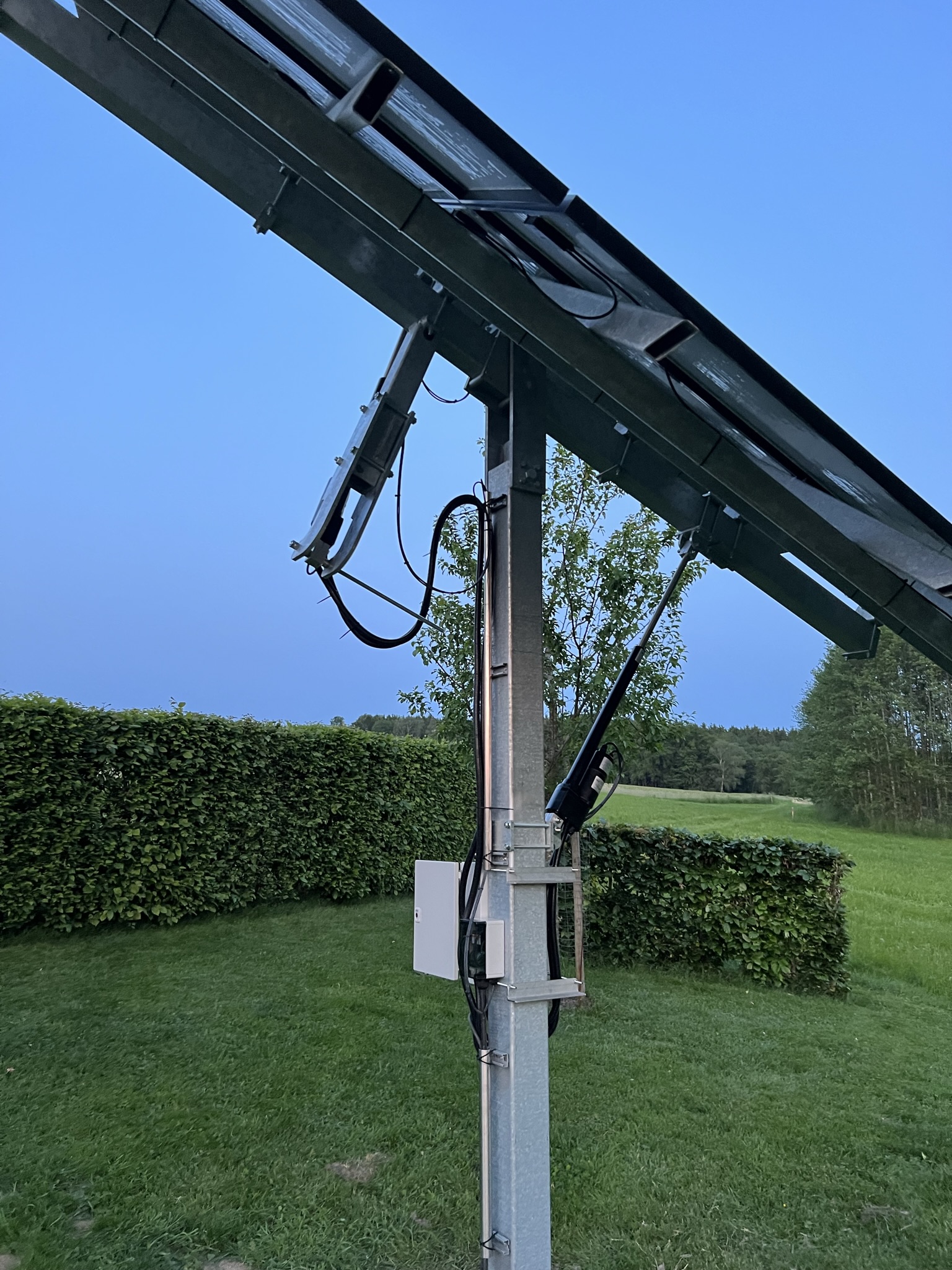
The project goal was to design a full-sized photovoltaic system that automatically aligns its panels with the sun.
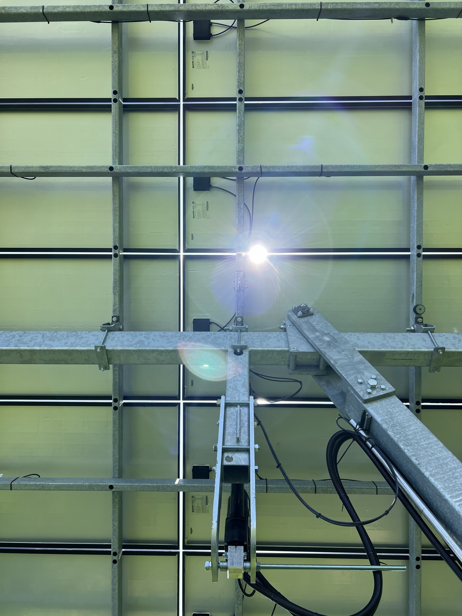
The system does not rotate around its own axis like other systems, but tilts each axis (north-south and east-west) individually. This allows for much cheaper linear motors instead of a slewing ring. The obtained energy is then fed into a battery system inside the house, or into the power grid if the battery is full.
The software is based on astronomical calculations which checked against real world data during development. The functionalities should principally work everywhere, as the coordinates of the location can be configured. The time information is received via NTP and stored in the internal RTC of the Arduino Opta's CPU.
This description will focus on the software side of the project. The CAD files are attached in .stp-format at the end of the article.
Functionalities of the program
The loop of the program consists of six steps:
- 1. Calculate azimuth and elevation angle
- 2. Calculate angles of the motors (north-south, east-west)
- 3. Print the results to the console
- 4. Set the motors to the calculated angles
- 5. Synchronize the RTC via NTP protocol
- 6. Wait for 5 minutes
While waiting for the next iteration, the program reads a digital value from the storm port (port 7). If the value is HIGH, then a storm is assumed and the panels go into default position (horizontal) for 30 minutes. The default position is also maintained during night hours.
Challenges
The first approach of the software calculated the angles of the sun (azimuth and elevation) based on the astronomical time and the location. These calculations can be found here: https://gml.noaa.gov/grad/solcalc/calcdetails.html
This information then was used to calculate the angles of the north-south and east-west component of our system using some basic trigonometric functions. However, we found that we could not just blindly take over these values, as the PV plant does not point directly to the sun, but rather always faced south.
We solved this problem by again using some basic trigonometry. Using a 3D model out of paper, we created formulas to calculate the swing angle (horizontal angle) between the south faced PV plant and the sun and also the inclination angle (like elevation, only in south direction). The formulas can be seen in the function calculateMotorAngles .
Now, we first calculate the azimuth and elevation of the sun, then calculate the angles of the motors and then calculate the position of the motors in mm. The offsets of the motor angles result from the construction plans.
The position of each motor is read as analog value from a potentiometer. This information however was not accurate enough. It could be related to a voltage drift of the measurement circuit. As a quick fix, we introduced a correction factor, which makes the measurements somewhat accurate again.
EXPANDED TECHNICAL DETAILS
This project scales up into serious electrical engineering, requiring careful management of high currents and voltages. A key component is the Maximum Power Point Tracking (MPPT) system, which optimizes the power harvested from the solar panels.
High-Amperage Telemetry (INA219)
You cannot use an Arduino's standard Analog pin to measure the high voltages and currents involved. Direct connection would damage the microcontroller.
- The system uses a Voltage Divider circuit with large resistors to safely scale the ~20V solar panel output down to a safe level for the Arduino's ADC.
- For precise current measurement, it employs an INA219 I2C Current Sensor.
- The high-current cables from the solar array physically run through the INA219 chip.
- The chip measures the tiny voltage drop across an integrated, high-power shunt resistor, allowing it to calculate the exact Current (Amps) and Power (Watts) flowing into the battery with high precision and speed.
The PWM Charge Controller Logic
Connecting a solar panel directly to a battery is dangerous. An unregulated 20V input will overcharge a 12V battery, causing it to boil, release explosive hydrogen gas, and be destroyed.
- The Arduino acts as an intelligent Charge Controller.
- The main
loop()constantly reads the battery voltage. if (batteryVolts < 12.0)-> The battery is deeply discharged. The Arduino commands a Heavy Duty P-Channel MOSFET to open fully via PWM (analogWrite(255)), allowing maximum solar current to rush in for bulk charging.if (batteryVolts >= 14.4)-> The battery is fully charged. The Arduino instantly reduces the PWM signal to a tiny trickle (e.g.,analogWrite(20)) to maintain a safe "Float" voltage, preventing overcharge and battery damage.
Industrial Grid Components
- Arduino Mega or ESP32: Used for processing complex tracking algorithms, driving displays, and handling Wi-Fi for data logging.
- INA219 or INA226 High Side I2C Current/Voltage Sensors: For robust energy telemetry.
- Heavy Duty P-Channel MOSFETs (like IRF4905): Mounted on large aluminum heat-sinks to dissipate the significant heat generated when switching high currents.
- Large 50W to 100W 18V Monocrystalline Solar Panels.
- 12V Deep Cycle SLA (Sealed Lead Acid) Battery.
SAFETY WARNING: Improper charge controller logic or MOSFET failure can cause a Lead Acid battery to violently vent explosive gas or catch fire. All logic states and hardware must be thoroughly verified before deployment.
Result
The result of our efforts is a power plant with a peak power of 3.15 kW and peak production per day of ~32 kWh. It accurately follows the sun and is field tested for over 9 months now.