This project is an easy introduction to stepper motors and aims to introduce null-level beginners to stepper motors and their respective drivers.
This project used 28byj-48 stepper motor and UNL-2003 stepper motor driver.
This project is based on the arduino UNO microprocessor.
Schematic of circuit
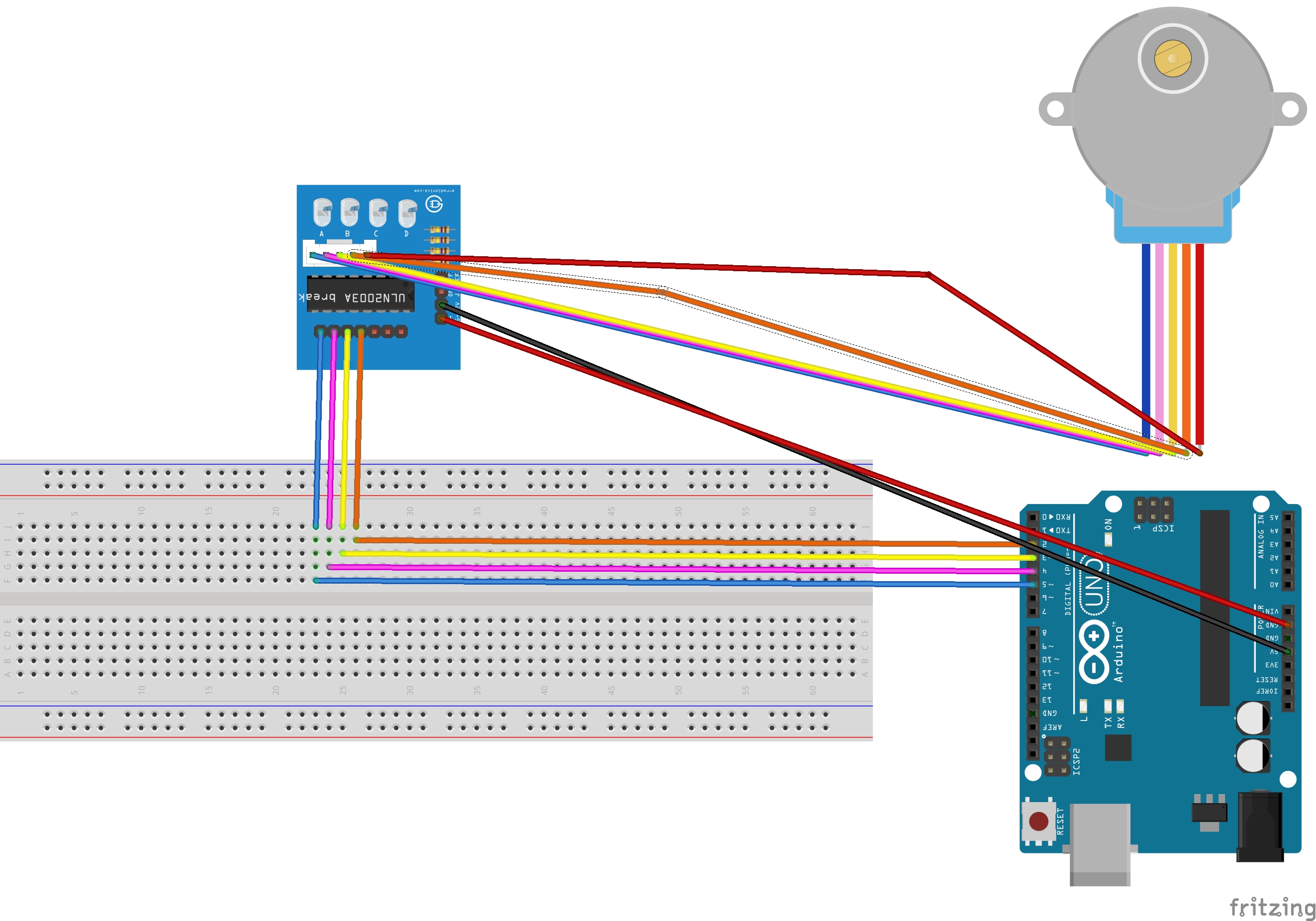
Follow the schematic given above. The connections are:
Stepper Motor :
Usually the female header pins of the motor are grouped and connected to the corresponding port on the uln-2003 but there can be exceptions, follow the diagram above. (view enlarged, it will help a lot!)
Arduino and Driver:
Any digital pins of your choice can be connected to the driver, starting from left for Coil A, B, C, D There are pins for E, F and G too, but we will not be using those for this project.
Connect the + port to the 5v port of the arduino, (if you wish you can also connect to the 3.3v) and the - port to the GND port of the arduino. (There are multiple GND ports, select any one.)
How the Stepper motor works
The stepper motor works by applying pulses of current respectively to each of the coils of the motor which each move the stepper motor one small step. Using this sequence repeatedly we generate movement which can be monitored to incredible levels of accuracy without PWM outputs.
Here we use the eight-phase model which energizes each coil respectively sometimes two at once. There is no need for PWM outputs here as the pulses are digital 1 or 0.
The order in which we apply the power affects the direction of the motor. If we apply power sequentially from A to D the motor turns clockwise while if we apply power sequentially from D to A the motor turns anti-clockwise.
Code
#define A 2
#define B 3
#define C 4
#define D 5
#define NUMBER_OF_STEPS_PER_REV 512
This segment defines the pins connected to each coil.
We are using 512 steps per revolution for this stepper motor.
Change this number to whatever your one is of.
void setup(){
pinMode(A,OUTPUT);
pinMode(B,OUTPUT);
pinMode(C,OUTPUT);
pinMode(D,OUTPUT);
}
This segment initializes each pin as output pin.
void write(int a,int b,int c,int d){
digitalWrite(A,a);
digitalWrite(B,b);
digitalWrite(C,c);
digitalWrite(D,d);
}

void onestep(){
write(1,0,0,0);
delay(5);
write(1,1,0,0);
delay(5);
write(0,1,0,0);
delay(5);
write(0,1,1,0);
delay(5);
write(0,0,1,0);
delay(5);
write(0,0,1,1);
delay(5);
write(0,0,0,1);
delay(5);
write(1,0,0,1);
delay(5);
}
This segment does all the actual work. The onestep function energizes each coil in turn to produce movement. The delays in between determine the speed of onestep.
void loop(){
int i;
i=0;
while(i<NUMBER_OF_STEPS_PER_REV){
onestep();
i++;
}
This segment will turn the motor one full turn (clockwise).
EXPANDED TECHNICAL DETAILS
Precision Motion Control Hub
This guide provides the technical blueprint for achieving sub-degree rotational accuracy using the low-cost 28BYJ-48 geared stepper motor.
- 4-Phase Unipolar Sequencing: The Arduino manages the ULN2003 driver's four inputs. The firmware implements "Half-Step" sequencing, providing 4096 steps per full 360-degree rotation of the internal geared shaft.
- Backlash Compensation Kernel: Geared steppers often have mechanical "Slop." The Arduino includes a software routine that adds a few extra steps whenever the motor reverses direction, maintaining perfect alignment for miniature CNCs or telescopes.
Hardware
- Integrated Driver Mapping: Detailed the physical wiring between the Arduino digital pins and the IN1-IN4 pins of the ULN2003 module, with power provided by an external 5V-12V supply to protect the Arduino.