Project Overview
"Guide to Modular Firmware" is a masterclass in embedded software engineering, specifically designed for developers who have outgrown basic Arduino sketches and are struggling with the mounting complexity of large-scale C/C++ projects. While many tutorials focus on "making it work," this guide focuses on "making it maintainable." By applying professional software design principles—such as encapsulation, isolation, and interface-based programming—to a simple LED animation project, the author demonstrates how to transform unreadable code into a professional, modular architecture.
This article is for embedded software developers with a solid working knowledge of C or C++, but who struggle with large and complex projects.
If you learn to develop embedded code, e.g. using the Arduino IDE, you find plenty of small example programs. It is helpful to get things started quickly, but as soon as your project begins to grow, help related to software design is rare.
In contrast, when you learn software development for desktop applications, project structures and software design is an integral part of the learning process.
In this short article, I will give you a simple guide on how you can build a modular structure for your firmware. This will keep your code clean and maintainable for large and complex projects.
Refactor your Code
If you start a new project, you can already prepare the structures as described. For this article, I will assume that you already have a working firmware but need to improve the code quality.
Improving your code in an iterative process is called refactoring. Testing is an integral part of this process: after each small change, you need to test whether the software is still working as expected.
In desktop application development, there are unit tests to ensure the integrity of smaller modules. I found it difficult to apply unit tests to embedded code, if not for small independent functions or modules. Therefore, you must use a simple run-time test of your software to ensure it is still functioning properly.
Refactoring only changes the code, but not the functionality. Even if you change names, move code around, or change implementations, the function of your code stays exactly the same. It is important that you either change or extend functionality or do refactoring, but you should never do both at the same time (or in the same commit).
Use a Version Control System
Changing your code without version history is a bad idea. If you do not already manage your code in a version control system, now is the time to start using one!
If you have never used a version control system before, use GIT and read one of the many tutorials on how to use it. There are graphical user interfaces for any operating system, so you do not need to work on the console. It does not matter how you manage your code, but rather that you implement a version control system.
After each small successful change, you should commit a new version. If you run into difficulty at a later stage, you can easily analyse every applied change to the code and go back to the last working version.
Demo Setup
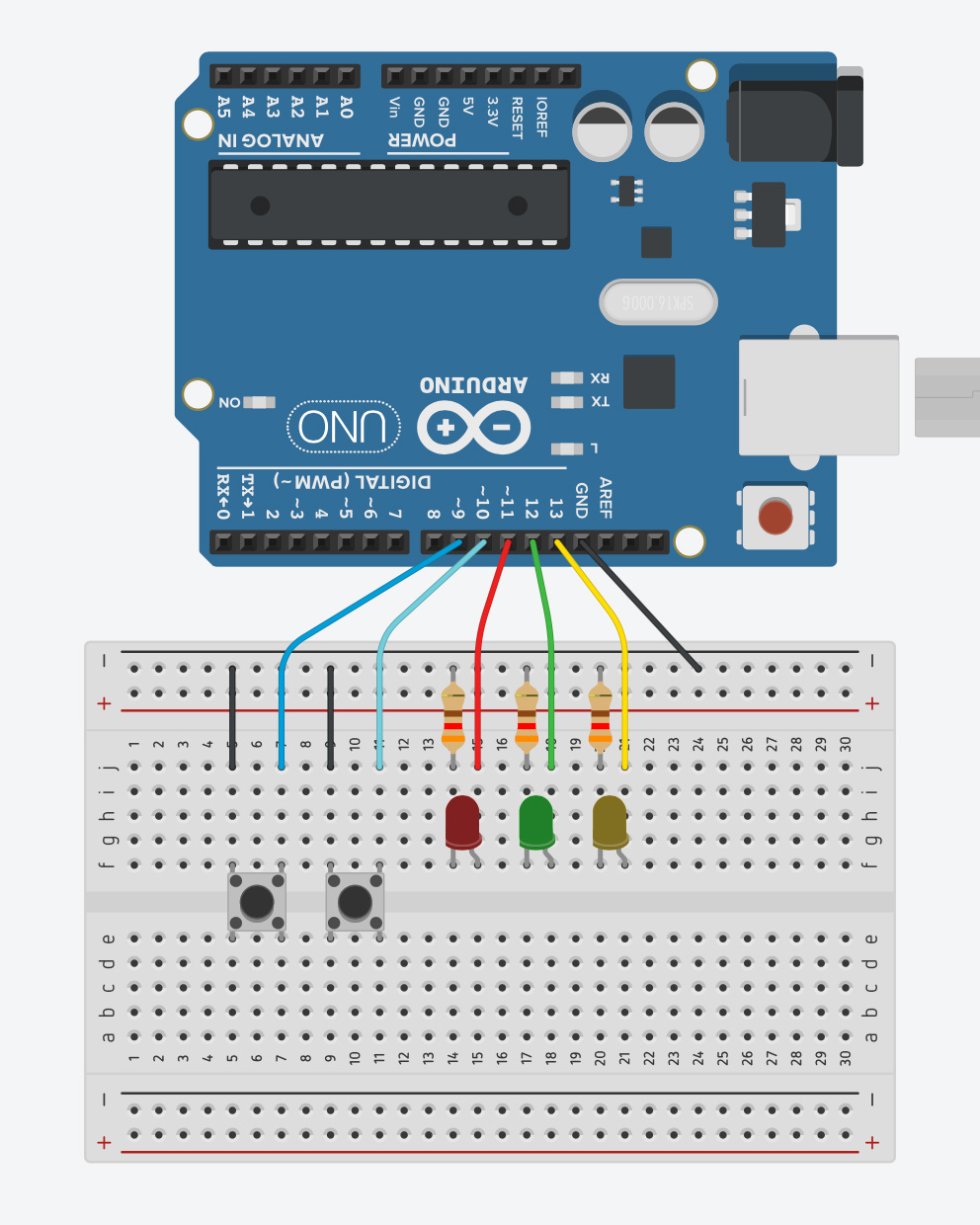
If you like to follow along using the real demo setup, you will first need an Arduino Uno, three LEDs with matching resistors and two pushbuttons. The example code expects a circuit as shown in the next illustration.
A Shockingly Bad Example to Start
The example code we start with is something I unfortunately see quite often. Please open a second browser window with the code at the following URL:
https://github.com/LuckyResistor/guide-modular-firmware/blob/master/fade_demo_01/fade_demo_01.ino
I cannot use a highly complex firmware for this article, and your source code may be in a different state. Nevertheless, this example code contains most of the elements I would like to discuss.
Because of the length of the code, I will simply link to the full examples. The code snippets in the article should have the correct line numbers, so you can easily find the locations.
Read the Example Code
Try to read the example code and determine its purpose before testing it. Here, there is no documentation, no functions and, therefore, no structure that would provide any hints.
Reading and understanding the code will likely take some time because of the unnamed literals and nested control statements.
Compile and Upload
If you set up the hardware for the demo, compile and upload it to the board. Otherwise, you can just follow along. There is no need to actually have a working circuit.
The firmware here is working just fine: there is an animated pattern on the three LEDs, and you can easily use the two buttons to switch between four different animations.
Here lies the problem with embedded development: if the device seems to work as expected, nobody asks if the code is written modular and in good quality.
What is a Module?
In the context of desktop software development, UML typically defines the terminology used to talk about design. When using UML, we would talk about a component with interfaces. I often use the term module in a similar sense.
In firmware, a module is code which has an interface and encapsulates its functionality:
- In C, a module is a compiling unit with a header, implementation file and several functions that build the interface.
- In C++, it can be a compiling unit with a header and implementation file…
- … and several functions in a namespace that build the interface.
- …with a class declaration as interface.
It is important to understand that the module encapsulates its functionality in a way that creates a level of abstraction. There is always the user of the module, and this user only has access to the interface of the module.
A module may depend on the interfaces of other modules, but never depends on code of the module’s user.
This principle is called interface-based programming, which is a vitally important design concept.
The Current State of the Example

How to Proceed
At this point, we should start refactoring the existing code and building new modules. This is an iterative process:
1. Encapsulate a piece of functionality:
- Move from low-level to high-level (bottom-up).
- Refactoring should never change the functionality.
2. Test the revised code.
3. Commit the change.
4. Repeat.
Encapsulate the Hardware Access
The lowest level in our code contains the parts directly accessing registers, as shown in the setup() function:
void setup() {
  // Initialize Timer
  TCCR2A = 0;
  TCCR2B = 1;
  OCR2A = 0;
  OCR2B = 0;
  TIMSK2 = _BV(TOIE2);
  // Ports
  DDRB |= 0b00111000;
  DDRB &= ~0b00000110;
  PORTB &= ~0b00111000;
  PORTB |= 0b00000110;
}
There are two major parts accessing the hardware:
- Control the LED brightness using software PWM.
- Detect button presses.
Create a “Display” Module
We want to start with the first part in order to control the brightness of the device’s individual LEDs. Not the animation, just the lowest level of functionality.
Before I write any implementation or apply changes, I should think about the interface, which is required for the functionality.
Technical Engineering Analysis
Modularizing firmware is not just about aesthetics; it is about managing cognitive load and ensuring long-term software stability.
- Hardware Abstraction Layer (HAL) Elevation: The guide moves from low-level register manipulation (
TCCR2A,OCR2B) to a clean, semantic API. By wrapping these registers in aDisplaymodule, the primary application logic no longer needs to know that "Pin 13 is actually Port B, Pin 5." This abstraction allows the code to be ported to different hardware (e.g., from an ATMega328P to an ESP32) simply by swapping the implementation file while the interface remains constant. - The Bottom-Up Refactoring Strategy:
- Isolation: Identify high-risk segments (ISR handlers, direct I/O) and move them into isolated compile units.
- Interface Design: Use
namespacesin C++ to avoid global scope pollution—a common source of bugs in large Arduino projects. - Encapsulation: Using
volatilecorrectly in theDisplaymodule ensures that variables used within Interrupt Service Routines (ISRs) are always fetched from memory, preventing compiler optimization errors.
- Decoupling Input from Logic: Instead of hard-coding action logic inside a button-check loop, the guide introduces a Callback Pattern. By using
typedef void (*Function)();, theButtonsmodule becomes completely generic; it only knows how to detect a press, while themainmodule decides what that press actually does. - Scaling with Class Hierarchies: Transitioning from a massive
switch-casestatement to a Class Hierarchy for animations (Fade,Roll,Blink) demonstrates the power of polymorphism. While virtual methods add a small amount of flash overhead (~800 bytes), they provide the ultimate modularity: a new animation can be added without modifying a single line of the original state machine. - Optimization via Data-Driven Design: The clean-up phase highlights how repetitive code (multiple
ifstatements for different LEDs) can be optimized into Data-Driven Loops using arrays of bit-masks. This technique not only makes the code cleaner but also reduces the footprint of the instruction cache, potentially speeding up execution.
Impact of Modular Design
The final result is a "main" module (fade_demo.ino) that is stripped down to its core intent: initializing subsystems and progressing the loop. This high-level readability allows engineers to identify architectural flaws or logic errors within seconds, rather than digging through hundreds of lines of nested if statements and bitwise operations.