Promoting Hygiene with Tech: The 20-Second Hand Wash Timer
Hand hygiene is one of the most effective measures to prevent the spread of diseases like COVID-19. However, most people underestimate the time required for a truly hygienic wash. This project implements the WHO-recommended 20-second rule into a simple, automated Arduino device designed for use in homes, schools, and offices.
User Interface: I2C LCD and Visual Indicators
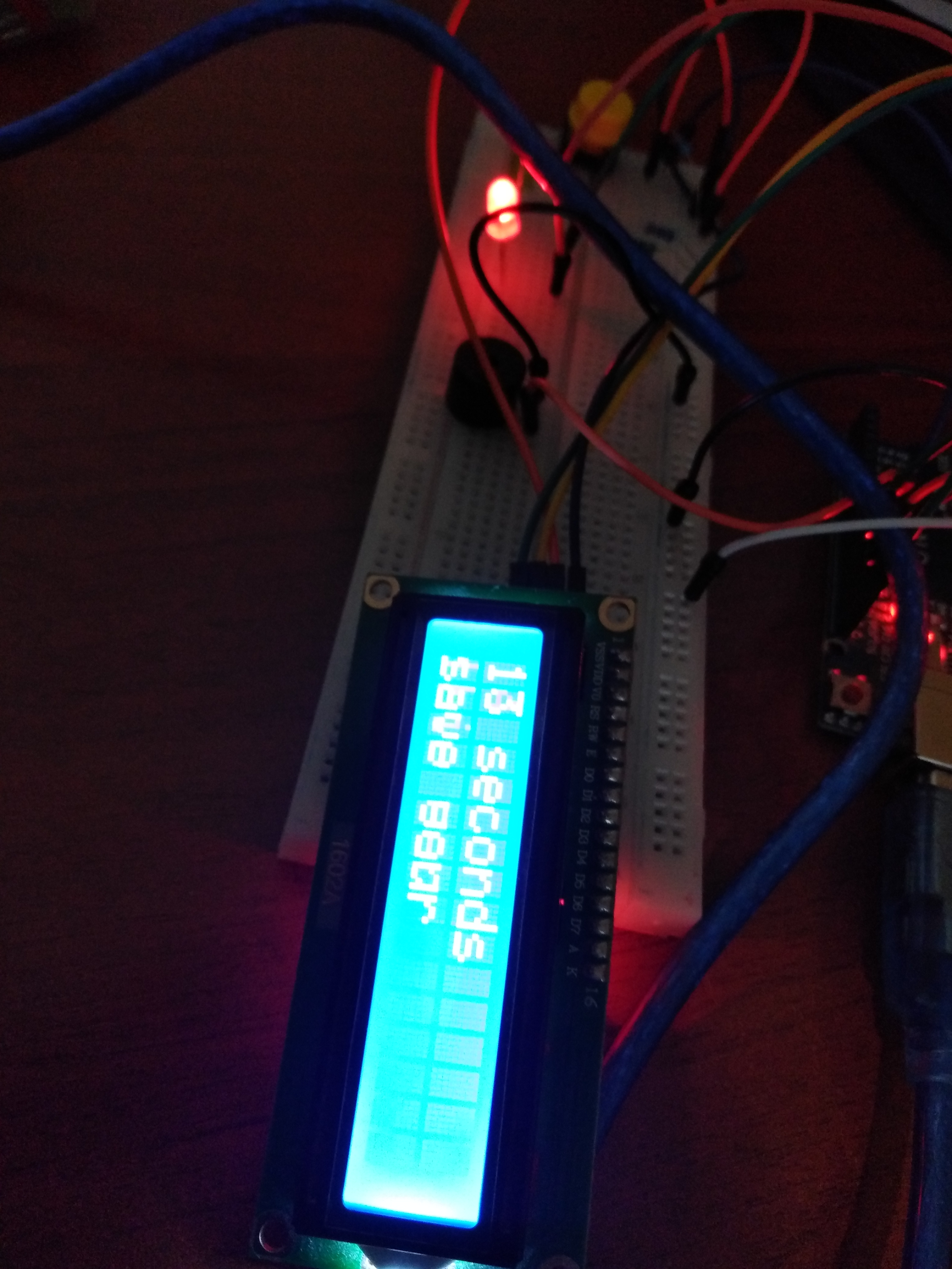
The project uses a 16x2 I2C LCD Module, which is superior to standard LCDs because it only requires 4 wires (SDA, SCL, VCC, GND) instead of the usual 16.
- Standby State: The Red LED indicates the system is ready and waiting.
- Active State: Upon pressing the button, the Green LED illuminates, and the LCD displays a live countdown from 20 seconds.
- Completion State: Once the timer hits zero, a Piezo Buzzer sounds a series of tones, signaling that the wash is complete.
Robust Hardware Logic
Built around the Arduino Uno, the system utilizes a simple yet reliable logic flow:
- Button Input: Connected with a 10k ohm pulldown resistor to prevent floating signals on pin 10.
- Timing Loop: The code uses a
forloop with 1-second delays to decrement the counter, ensuring accuracy. - Low-Cost Components: By using generic LEDs, standard buzzers, and a basic breadboard layout, the project remains highly accessible for beginners and low-budget community hygiene initiatives.
Simplified Assembly and Deployment
The project is designed for rapid deployment. The I2C interface simplifies the wiring significantly, making it easy to mount the LCD into a waterproof enclosure near a sink. This "set it and forget it" tool serves as a persistent visual reminder of health best practices.
This project is a simplified handwashing timer with basic components, I have thought it because I wanted to do a project to prevent covid but simple, low cost and accessible in arduino stores.
This project works like this: press the button and the code will turn it on, the timer will start counting, it will last 20 seconds and it will start ringing when finished.
An image
How to build the project:
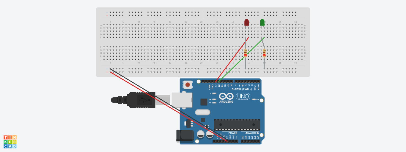
1. Ride the lights.
The red led connected to pin 13, green led to pin 12 and both connected to ground with a resistance and gnd connect to the negative side of the bread board
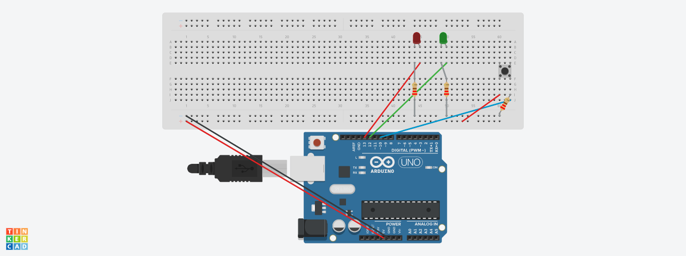
2. Mount button.
Connect pin 5v to the positive part of the breadboard also connect to pin 10 with 10k ohm resistance to ground
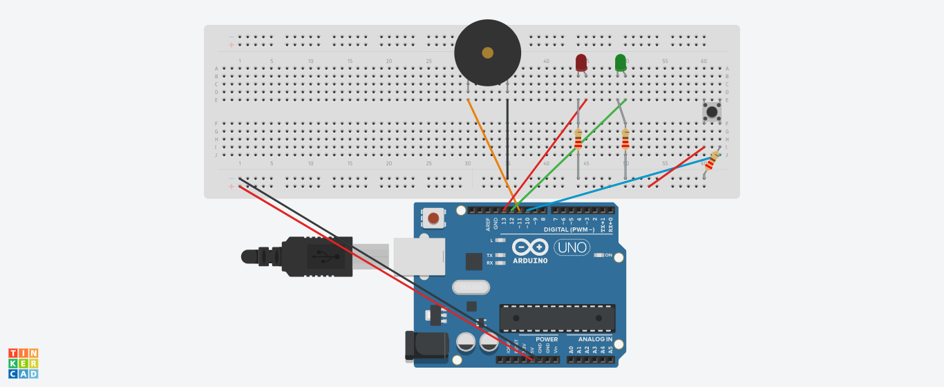
3. Mount the buzzer
connect pin 11 to positive part and with ground wire
4. Finally place the LCD I2C like this:
SDA to SDA
SCL to SCL
VCC to 5V
GND to GND
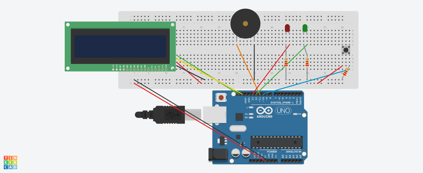
And so it is done