Main article: https://paulplusx.wordpress.com/2016/03/03/rtpts_hw/. The RTPT uses GPS coordinates and high-precision servos to point a laser at any planet in the solar system. It is a powerful example of how Arduino Mega can handle the heavy lifting of astronomical telemetry.
Celestial Navigation: The RTPT Vision
The Real-Time Planet Tracker (RTPT) is a sophisticated hardware-software integration designed to bridge the gap between abstract mathematical coordinates and physical reality. While most planetarium apps show you where Mars or Venus is on a screen, the RTPT uses an automated Pan-Tilt laser mechanism to physically point towards those planets in the night sky (or on a ceiling for educational use). By combining GPS precision with advanced servos, this project creates a "Personal Observatory" that adapts to your exact location on Earth.
Things you need:
- Arduino Mega (or MCU with more than 33Kbyte flash). This is important because my final code was around 33KB and I couldn't fit it in an UNO.
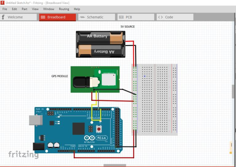
- U-BLOX GPS Receiver (NEO-6M) or any GPS Module.
- MPU9250 (9 axis gyro-accelero-magneto) for auto Yaw stabilization (optional)
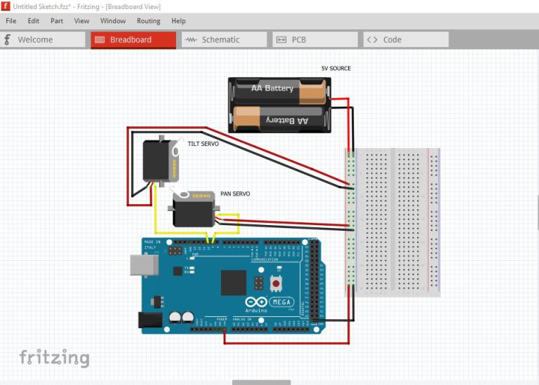
- Pan-tilt Mechanism with Servos (pan servo should be of 3.5 turns and tilt servo can be a normal 180 degree servo)
- A laser pointer – to be fixed to the tilt servo to show planet location in a closed room
The Brain: Why Arduino Mega?
A common pitfall in advanced telemetry projects is exceeding the memory limits of the Arduino Uno. This project explicitly utilizes the Arduino Mega 2560 because the final binary exceeds 33KB. The Extra Flash memory is essential for:
- TinyGPS++ Mastery: Processing NMEA sentences from the U-BLOX NEO-6M requires significant string manipulation and buffer management.
- Ephemeris Calculations: Calculating the exact Right Ascension and Declination of planets involves complex floating-point math and mathematical libraries that quickly consume memory.
- Serial Multitasking: The Mega's multiple hardware serial ports (using
Serial2for GPS) ensure that tracking stays smooth without the latency associated with SoftwareSerial.
Starting with the GPS
Using the GPS is very easy when we use TinyGPS++ Libraries. GPS uses Serial communication, so I have connected it to Serial2 of Mega that is pin 16 and pin 17.
After connecting, burn a test code from library named “FullExample“. The library use Software serial, so make sure you have converted it to Serial2 - also change the GPSBaud to 9600. Here is the modified code. Understand this code properly because we will be using few important (not all) lines and functions (ex. SmartDelay() func to update gps values) from this code:
#include <TinyGPS++.h>
/*
This sample code demonstrates the normal use of a TinyGPS++ (TinyGPSPlus) object.
It requires the use of SoftwareSerial, and aSerial2umes that you have a
4800-baud serial GPS device hooked up on pins 4(rx) and 3(tx).
*/
static const uint32_t GPSBaud = 9600;
// The TinyGPS++ object
TinyGPSPlus gps;
void setup()
{
Serial.begin(115200);
Serial2.begin(GPSBaud);
Serial.println(F(“FullExample.ino”));
Serial.println(F(“An extensive example of many interesting TinyGPS++ features”));
Serial.print(F(“Testing TinyGPS++ library v. “)); Serial.println(TinyGPSPlus::libraryVersion());
Serial.println(F(“by Mikal Hart”));
Serial.println();
Serial.println(F(“Sats HDOP Latitude   Longitude   Fix  Date       Time     Date Alt    Course Speed Card  Distance Course Card  Chars Sentences Checksum”));
Serial.println(F(”          (deg)      (deg)       Age                      Age  (m)    — from GPS —-  —- to London  —-  RX    RX        Fail”));
Serial.println(F(“—————————————————————————————————————————————“));
}
void loop()
{
static const double LONDON_LAT = 51.508131, LONDON_LON = -0.128002;
printInt(gps.satellites.value(), gps.satellites.isValid(), 5);
printInt(gps.hdop.value(), gps.hdop.isValid(), 5);
printFloat(gps.location.lat(), gps.location.isValid(), 11, 6);
printFloat(gps.location.lng(), gps.location.isValid(), 12, 6);
printInt(gps.location.age(), gps.location.isValid(), 5);
printDateTime(gps.date, gps.time);
printFloat(gps.altitude.meters(), gps.altitude.isValid(), 7, 2);
printFloat(gps.course.deg(), gps.course.isValid(), 7, 2);
printFloat(gps.speed.kmph(), gps.speed.isValid(), 6, 2);
printStr(gps.course.isValid() ? TinyGPSPlus::cardinal(gps.course.value()) : “*** “, 6);
unsigned long distanceKmToLondon =
(unsigned long)TinyGPSPlus::distanceBetween(
gps.location.lat(),
gps.location.lng(),
LONDON_LAT,
LONDON_LON) / 1000;
printInt(distanceKmToLondon, gps.location.isValid(), 9);
double courseToLondon =
TinyGPSPlus::courseTo(
gps.location.lat(),
gps.location.lng(),
LONDON_LAT,
LONDON_LON);
printFloat(courseToLondon, gps.location.isValid(), 7, 2);
const char *cardinalToLondon = TinyGPSPlus::cardinal(courseToLondon);
printStr(gps.location.isValid() ? cardinalToLondon : “*** “, 6);
printInt(gps.charsProcessed(), true, 6);
printInt(gps.sentencesWithFix(), true, 10);
printInt(gps.failedChecksum(), true, 9);
Serial.println();
smartDelay(1000);
if (millis() > 5000 && gps.charsProcessed() < 10)
Serial.println(F(“No GPS data received: check wiring”));
}
// This custom version of delay() ensures that the gps object
// is being “fed”.
static void smartDelay(unsigned long ms)
{
unsigned long start = millis();
do
{
while (Serial2.available())
gps.encode(Serial2.read());
} while (millis() – start < ms); } static void printFloat(float val, bool valid, int len, int prec) { if (!valid) { while (len– > 1)
Serial.print(‘*’);
Serial.print(‘ ‘);
}
else
{
Serial.print(val, prec);
int vi = abs((int)val);
int flen = prec + (val < 0.0 ? 2 : 1); // . and – flen += vi >= 1000 ? 4 : vi >= 100 ? 3 : vi >= 10 ? 2 : 1;
for (int i=flen; i<len; ++i)
Serial.print(‘ ‘);
}
smartDelay(0);
}
static void printInt(unsigned long val, bool valid, int len)
{
char sz[32] = “*****************”;
if (valid)
sprintf(sz, “%ld”, val);
sz[len] = 0;
for (int i=strlen(sz); i<len; ++i) sz[i] = ‘ ‘; if (len > 0)
sz[len-1] = ‘ ‘;
Serial.print(sz);
smartDelay(0);
}
static void printDateTime(TinyGPSDate &d, TinyGPSTime &t)
{
if (!d.isValid())
{
Serial.print(F(“********** “));
}
else
{
char sz[32];
sprintf(sz, “%02d/%02d/%02d “, d.month(), d.day(), d.year());
Serial.print(sz);
}
if (!t.isValid())
{
Serial.print(F(“******** “));
}
else
{
char sz[32];
sprintf(sz, “%02d:%02d:%02d “, t.hour(), t.minute(), t.second());
Serial.print(sz);
}
printInt(d.age(), d.isValid(), 5);
smartDelay(0);
}
static void printStr(const char *str, int len)
{
int slen = strlen(str);
for (int i=0; i<len; ++i)
Serial.print(i smartDelay(0);
}
We will also be using few code lines from “Deviceexample” from Tinygps++ library. Here is the main code:
#include <TinyGPS++.h>
/*
This sample sketch demonstrates the normal use of a TinyGPS++ (TinyGPSPlus) object.
It requires the use of SoftwareSerial, and aSerial2umes that you have a
4800-baud serial GPS device hooked up on pins 4(rx) and 3(tx).
*/
static const uint32_t GPSBaud = 9600;
// The TinyGPS++ object
TinyGPSPlus gps;
void setup()
{
Serial.begin(115200);
Serial2.begin(GPSBaud);
Serial.println(F(“DeviceExample.ino”));
Serial.println(F(“A simple demonstration of TinyGPS++ with an attached GPS module”));
Serial.print(F(“Testing TinyGPS++ library v. “)); Serial.println(TinyGPSPlus::libraryVersion());
Serial.println(F(“by Mikal Hart”));
Serial.println();
}
void loop()
{
// This sketch displays information every time a new sentence is correctly encoded.
while (Serial2.available() > 0)
if (gps.encode(Serial2.read()))
displayInfo();
if (millis() > 5000 && gps.charsProcessed() < 10)
{
Serial.println(F(“No GPS detected: check wiring.”));
while(true);
}
}
void displayInfo()
{
Serial.print(F(“Location: “));
if (gps.location.isValid())
{
Serial.print(gps.location.lat(), 6);
Serial.print(F(“,”));
Serial.print(gps.location.lng(), 6);
}
else
{
Serial.print(F(“INVALID”));
}
Serial.print(F(”  Date/Time: “));
if (gps.date.isValid())
{
Serial.print(gps.date.month());
Serial.print(F(“/”));
Serial.print(gps.date.day());
Serial.print(F(“/”));
Serial.print(gps.date.year());
}
else
{
Serial.print(F(“INVALID”));
}
Serial.print(F(” “));
if (gps.time.isValid())
{
if (gps.time.hour() < 10) Serial.print(F(“0”));
Serial.print(gps.time.hour());
Serial.print(F(“:”));
if (gps.time.minute() < 10) Serial.print(F(“0”));
Serial.print(gps.time.minute());
Serial.print(F(“:”));
if (gps.time.second() < 10) Serial.print(F(“0”));
Serial.print(gps.time.second());
Serial.print(F(“.”));
if (gps.time.centisecond() < 10) Serial.print(F(“0”));
Serial.print(gps.time.centisecond());
}
else
{
Serial.print(F(“INVALID”));
}
Serial.println();
}
The reason why I am asking you to understand these codes is because we will be using SmartDelay to update GPS values from the GPS buffer:
static void smartDelay(unsigned long ms)
{
unsigned long start = millis();
do
{
while (Serial2.available())
gps.encode(Serial2.read());
} while (millis() – start < ms);
}
Also we will be using the following functions' call statements to get Latitude, Longitude, Year, Month, Date, Day, Hour, Minute:
gps.location.lat()
gps.location.lng()
gps.date.year()
gps.date.month()
gps.date.day()
gps.time.hour()
gps.time.minute()
Now that we have our GPS ready we can go for pan-tilt mechanism with Laser.
We need to get a 3.5 turns Servo for PAN and a normal 180° Servo for TILT. I won't tell you much about a servo pan-tilt mechanism, but rather focus on the connections and its mapping.
Principle: The mechanisms used in pan tilt are the same as the ones used for moving large telescopes in Space Observatory!
- The pan-tilt can rotate roughly 360° from side-to-side (pan motor) and can tilt up & downward (tilt motor) around 180°.
- A laser pointer will be mounted on this pan-tilt mechanism
- Calculated azimuth angle could be traced by pan motor; elevation angle traced by tilt motor.
First, for the connections, we will be using Pin 9 for Pan Servo and Pin 10 for Tilt Servo.
Precision Actuation: 3.5-Turn Servos
In tracking, "resolution" is everything. Instead of standard $180^\circ$ servos, the RTPT employs a HS-785HB multi-turn servo for the Azimuth (Pan) axis:
- Full Circle Coverage: A $3.5$-turn servo allows for a full $360^\circ$ of rotation with significantly more granularity than a standard servo.
- Software Mapping: The code uses a specialized
map()function to translate $0-360^\circ$ of Azimuth into a specific pulse-width range ($5-29$), ensuring the laser stays perfectly aligned with the target planet's real-world heading. - Laser Feedback: By mounting a laser pointer on the tilt axis, the system provides immediate visual confirmation of the planet's location, making it an incredible tool for STEM demonstrations.
Servo mapping
Just by looking at the servo library examples, you will understand how to make a servo work. We just need three lines of code from the library for each servo.
We need to define Servo objects and attach the pins and initialize them:
#include
Servo myservoAz; // create servo object to control a servo
Servo myservoEl;
myservoAz.attach(9); //Attach the pins
myservoEl.attach(10);
myservoAz.write(5);   //initialize the servo to go to its zero
myservoEl.write(2);   //for my servos it was 5 (for pan/azimuth servo) and 2(for tilt  servo)
Our pan servo is a 3.5 turn servo and it takes input from 5 to 29 to rotate from 0° to 360°. Then we do our mapping which is quit simple. Let's assume the variable “Azim” gives us the value of Azimuth and the variable “Elevation” altitude, then we do our mapping as:
Azi = map(Azim, 0, 360, 5, 29); //its for my 3.5 turn servo that gives a 36                                 0° turn runs on values 5 -29
Az = (int)Azi;
Elev = map(Elevation, -90, 90, 2, 178); //its for my 180° servo that runs on                                          values 0 -180
El = (int)Elev;
Azi and El are the right mappings and can be fed to the pan tilt as:
myservoAz.write(Az);
 myservoEl.write(El);
Now all you need to do is convert the calculation of Azimuth-Altitude from the previous post into an Arduino code and use the data from GPS and get the output and feed it to the servo.
Note: You must align your pan-tilt setup at its initial position (both at 0° ) with the 0° Azimuth of your actual location - that is nothing but North direction!
Integration Roadmap: GPS to Servo
The workflow is a masterclass in synchronous data handling:
- GPS Lock: Using
smartDelay(), the code "feeds" the GPS buffer while maintaining the calculation loop. - Coordinate Sync: The system pulls Latitude, Longitude, and current UTC time to calculate the observer's "Local Sidereal Time."
- Active Stabilization: If an MPU9250 is added, the system can automatically compensate for the base's orientation, meaning you don't even need to align the device with True North manually.
In the next post, I’ll integrate MPU9250 so that my Pan Servo automatically senses the north of my location and automatically shows me the planet position by adjusting itself even if I don't keep it at Azimuth 0° (again this step is optional).
The RTPT is a professional proof-of-concept that turns complex astronomical data into a tangible, interactive Experience.