
HC1 Mission Overview
Mission Name: HC1
Launch Date: TBD
Mission Objective : The primary objective of the HC1 mission is to collect and
analyze comprehensive data on the satellite's movements and orientation in space.
This data will be crucial for developing advanced satellite technologies and systems
for future missions with more complex payloads.
Mission Purpose: The HC1 satellite is designed to act as a testbed for various
motion and orientation sensors. By capturing high-precision data on the satellite's
behavior in orbit, the mission aims to enhance our understanding of satellite
dynamics. This information will be instrumental in designing more sophisticated
satellites with specific scientific, communication, or observational goals.
Key Goals:
1. Data Collection:
○ Gather detailed information on the satellite's linear acceleration,
angular velocity, and magnetic orientation.
○ Use this data to understand how the satellite moves and stabilizes in
space.
2. Sensor Testing:
○ Evaluate the performance and reliability of different motion and
orientation sensors under real space conditions.
○ Identify the best sensor combinations for future missions.
3. System Validation:
○ Test the integration and functionality of the satellite's onboard systems,
including power management, communication, and data processing
units.
○ Ensure that all systems work seamlessly together to support the
satellite's operational needs.
4. Foundation for Future Missions:
○ Use the data and insights gained from the HC1 mission to inform the
design and development of subsequent satellites.
○ Plan and execute more advanced missions with specific scientific or
practical applications based on the findings from HC1.
Mission Significance: The HC1 mission represents a critical step in the ongoing
development of satellite technology. By focusing on the precise measurement and
analysis of movement and orientation data, HC1 will provide invaluable insights that
will shape the future of satellite missions. This foundational mission will pave the way
for more specialized and ambitious projects, ultimately contributing to the
advancement of space exploration and utilization.
Expected Outcomes:
● A comprehensive dataset detailing the satellite's movements and orientation
in space.
● Enhanced understanding of the performance and integration of various
sensors and systems.
● Improved satellite design and operational strategies for future missions.
● Establishment of a solid knowledge base for subsequent satellite projects with
specific goals and applications.
Conclusion: The HC1 mission is dedicated to pushing the boundaries of our
knowledge in satellite motion and orientation. By meticulously collecting and
analyzing data from a suite of advanced sensors, HC1 will set the stage for future
satellite missions that are more targeted and capable. The success of HC1 will mark
a significant milestone in our journey to explore and utilize space more effectivel
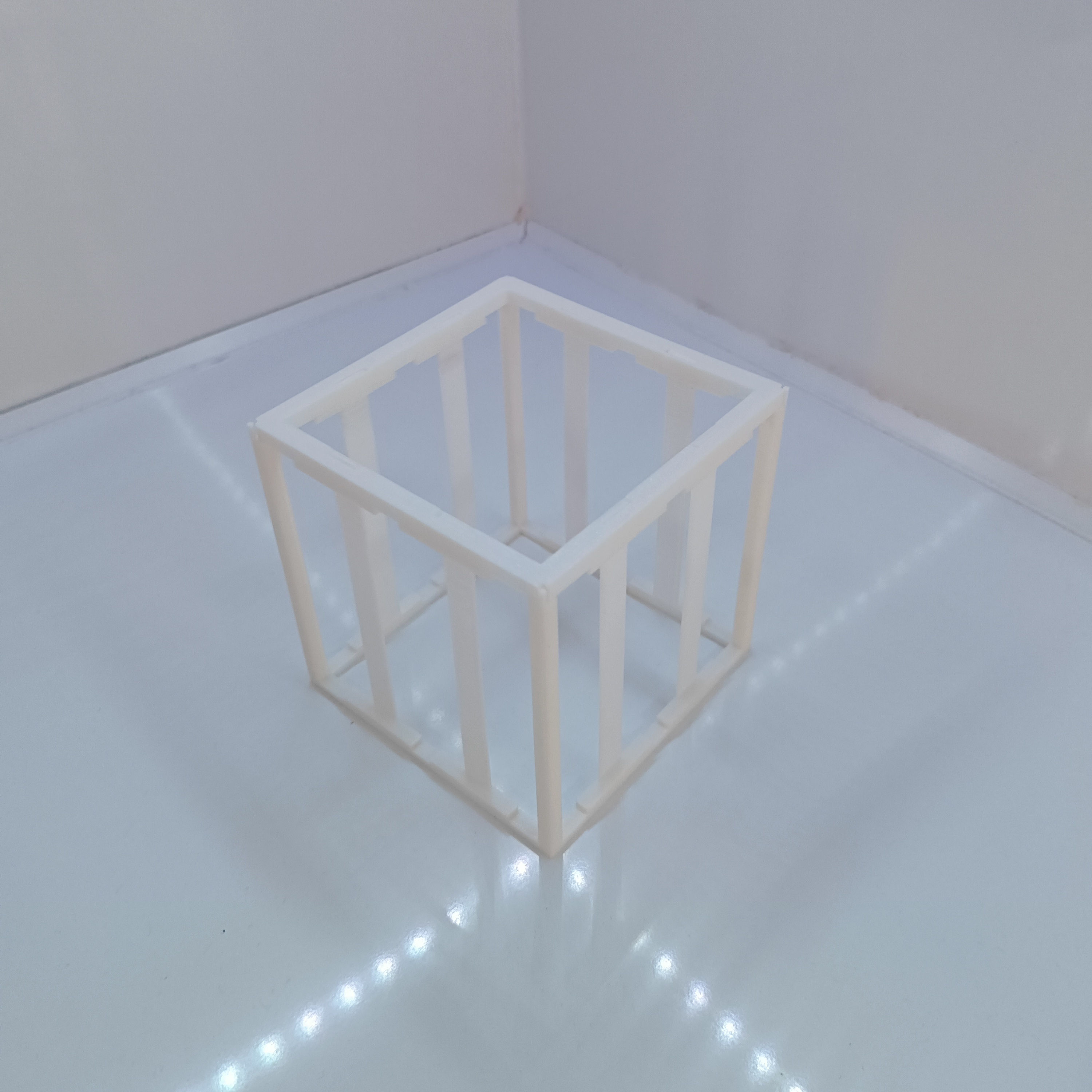
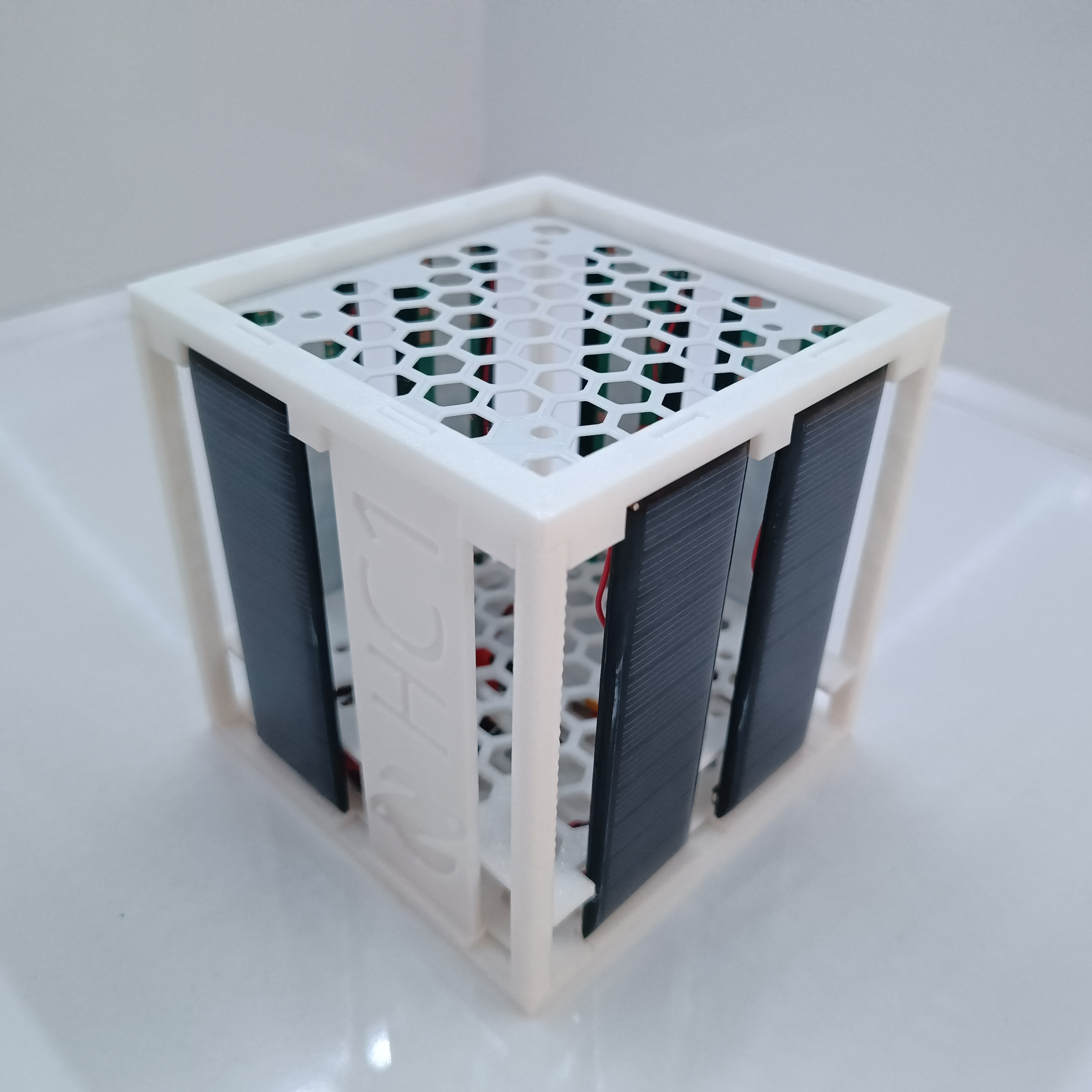
Light Tracking: The Helios Cube
The Helios Cube is a beautiful desktop kinetic sculpture. Instead of driving around on wheels, it uses a Pan/Tilt base to rotate its glowing crystalline structure toward the brightest light source in its environment, mimicking biological phototaxis (like a sunflower tracking the sun).
The Sensor Array Bridge
A single light sensor isn't enough to track movement; you need a differential array.
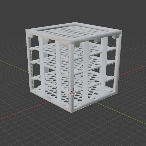
- You mount four LDRs (Photoresistors) on the four sides of a 3D-printed pyramid or cube (Top, Bottom, Left, Right).
- The Arduino reads all four analog pins continuously:
analogRead(A0)throughA3. - The Math: It calculates the difference between opposite sensors.
int horizontalDifference = leftSensor - rightSensor;int verticalDifference = topSensor - bottomSensor;
Kinematic Execution
Once the differences are established, the Arduino drives two Micro Servos (SG90).
- If
horizontalDifference > 50(The left side is significantly brighter): The Arduino commands the Azimuth (Pan) servo to swing left until the sensors equalize. - By placing this inside an active
whileloop, the cube fluidly and continuously tracks a flashlight beamed across the room!
System Hardware
- Arduino Uno/Nano: The processor.
- 4x Light Dependent Resistors (LDR).
- 2x Micro Servos on a Pan/Tilt bracket.
- NeoPixels: (Optional) Placed inside the translucent cube to change colors based on how much light it is capturing!
HC1-A-V-1.00.3
Abstract
This paper presents an implementation of a comprehensive environmental
monitoring system utilizing Arduino-compatible GNSS, geomagnetic, and inertial
sensors. The system integrates DFRobot's GNSS, BMM150 geomagnetic sensor,
and BMI160 accelerometer/gyroscope to provide accurate geolocation, orientation,
and motion data. The sensors communicate using I2C protocol, and the data is
processed and displayed via Serial Monitor. This setup can be extended for
applications in navigation, wearables, and environmental data logging.
1. Introduction
Environmental monitoring is critical in various applications, ranging from navigation
systems to fitness tracking. Accurate data collection regarding position, orientation,
and motion enhances the functionality and reliability of these applications. This paper
details the integration of GNSS, geomagnetic, and inertial sensors with an Arduino
microcontroller, providing a robust solution for comprehensive environmental
monitoring.
2. System Components
2.1. GNSS Module The GNSS module provides geolocation data, including latitude,
longitude, altitude, and the number of satellites used. It supports multiple GNSS
systems (GPS, BeiDou, GLONASS) to ensure reliable positioning.
2.2. Geomagnetic Sensor (BMM150) The BMM150 geomagnetic sensor measures
the Earth's magnetic field across three axes (x, y, z). This data is used to determine
the compass heading and can be combined with other sensor data for enhanced
orientation tracking.
2.3. Inertial Measurement Unit (BMI160) The BMI160 includes an accelerometer
and gyroscope, providing motion and orientation data. It is capable of counting steps,
which is useful in fitness applications and wearable devices.
3. Methodology
3.1. Hardware Configuration The sensors are connected to the Arduino using the I2C
protocol, which allows for efficient and straightforward communication. The GNSS
module is powered and configured via the I2C interface, and similar procedures are
followed for the BMM150 and BMI160 sensors.
3.2. Software Implementation The software, written in C++ for the Arduino
environment, initializes and configures the sensors, collects data, and prints it to the
Serial Monitor. Error handling mechanisms ensure robust operation even in the event
of sensor initialization failures.
3.3. Data Processing and Output The collected data includes:
● GNSS: UTC time, date, latitude, longitude, altitude, speed over ground, and
course over ground.
● BMM150: Magnetic field data (x, y, z) and compass heading.
● BMI160: Step count and motion data.
The data is processed and output to the Serial Monitor, providing a comprehensive
overview of the environmental conditions.
5. Results and Discussion
The system successfully integrates and collects data from the GNSS, BMM150, and
BMI160 sensors. The GNSS module provides accurate geolocation data, while the
BMM150 sensor offers reliable geomagnetic readings, and the BMI160 sensor tracks
motion and step count. This comprehensive data collection enables robust
environmental monitoring, useful in various applications such as navigation,
wearable devices, and environmental data logging.
6. Conclusion
This paper presents a successful integration of GNSS, geomagnetic, and inertial
sensors using an Arduino microcontroller. The system demonstrates reliable
performance in collecting and displaying comprehensive environmental data. Future
work includes extending this setup to incorporate additional sensors and developing
algorithms for advanced data fusion and analysis.
7. References
● DFRobot GNSS Library: DFRobot_GNSS.h
● DFRobot BMM150 Library: DFRobot_BMM150.h
● DFRobot BMI160 Library: DFRobot_BMI160.h
● Arduino Documentation: Arduino