Premise:
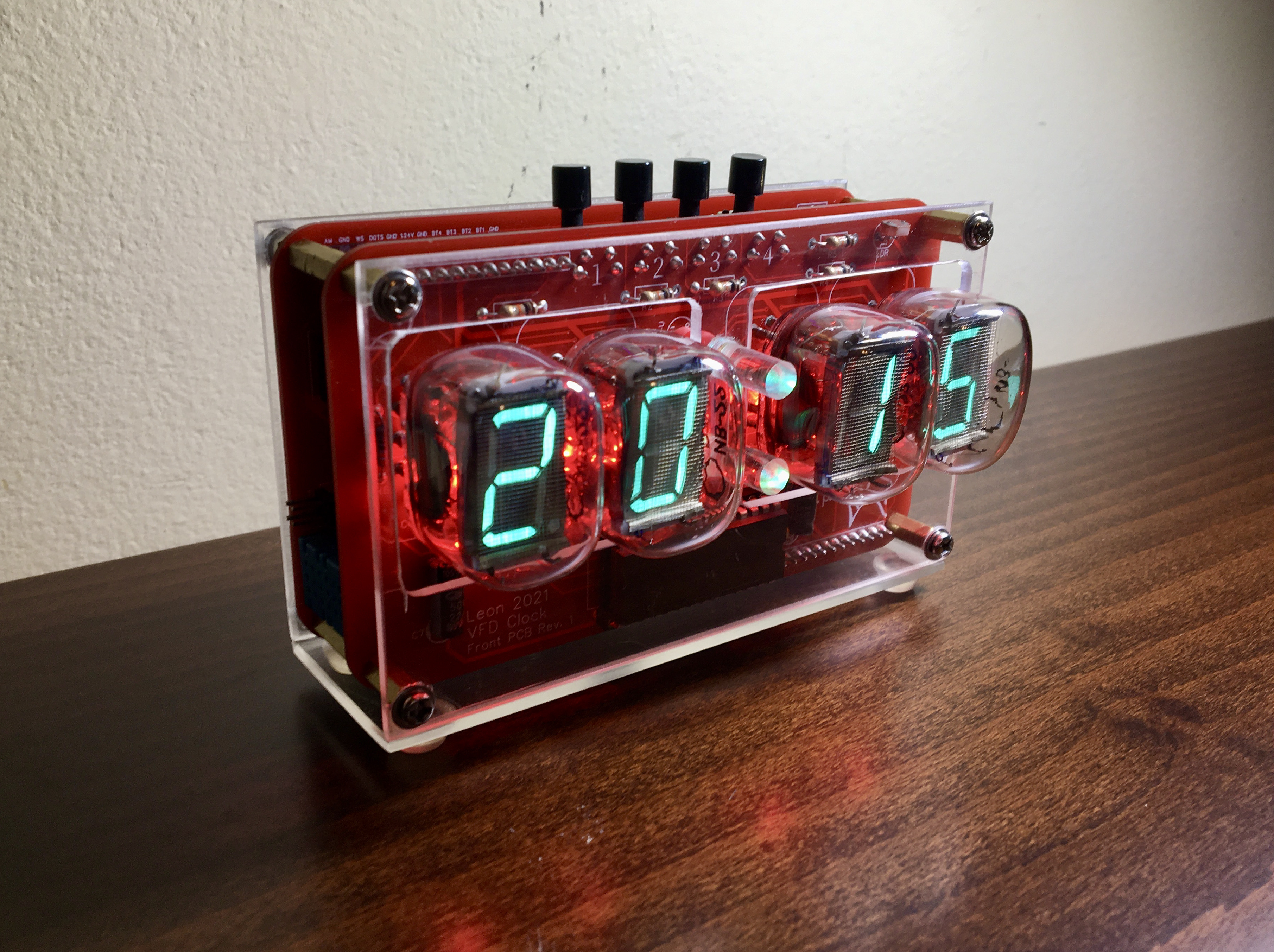
Many of you probably know how these things go: you start with making a nixie clock and you end up with a self full of Soviet tube clocks! That's what happened to me as well: while researching nixie tubes I found out about VFDs, the display technology that replaced nixies. At that time I knew what my next project would be. Unlike with nixies, I'm old enough to remember this bright cyan segmented displays being everywhere, from cars to Hi-Fi sound systems, back when I was a kid. Nostalgia aside, this retro yet futuristic contradictory vibe that they have is appealing to me. VFDs it was then!
Being an amateur in electronics and completely self taught, I try to make every new project be a step forward from the last. My nixie clock was made on a perfboard utilizing an Arduino Mega and ready made power supplies (if you are interested in checking it out here is the link: https://create.arduino.cc/projecthub/deathorion/diy-nixie-clock-on-perfboard-7c47d1?ref=search&ref_id=perfboard%20nixie%20clock&offset=0 )
So, for the VFD clock I decided to design my own PCBs and power supplies. Luckily, there are a lot of free PCB designing tools out there and many services that can cheaply built your PCBs. I used EasyEDA for the design which is indeed easy to use and free.
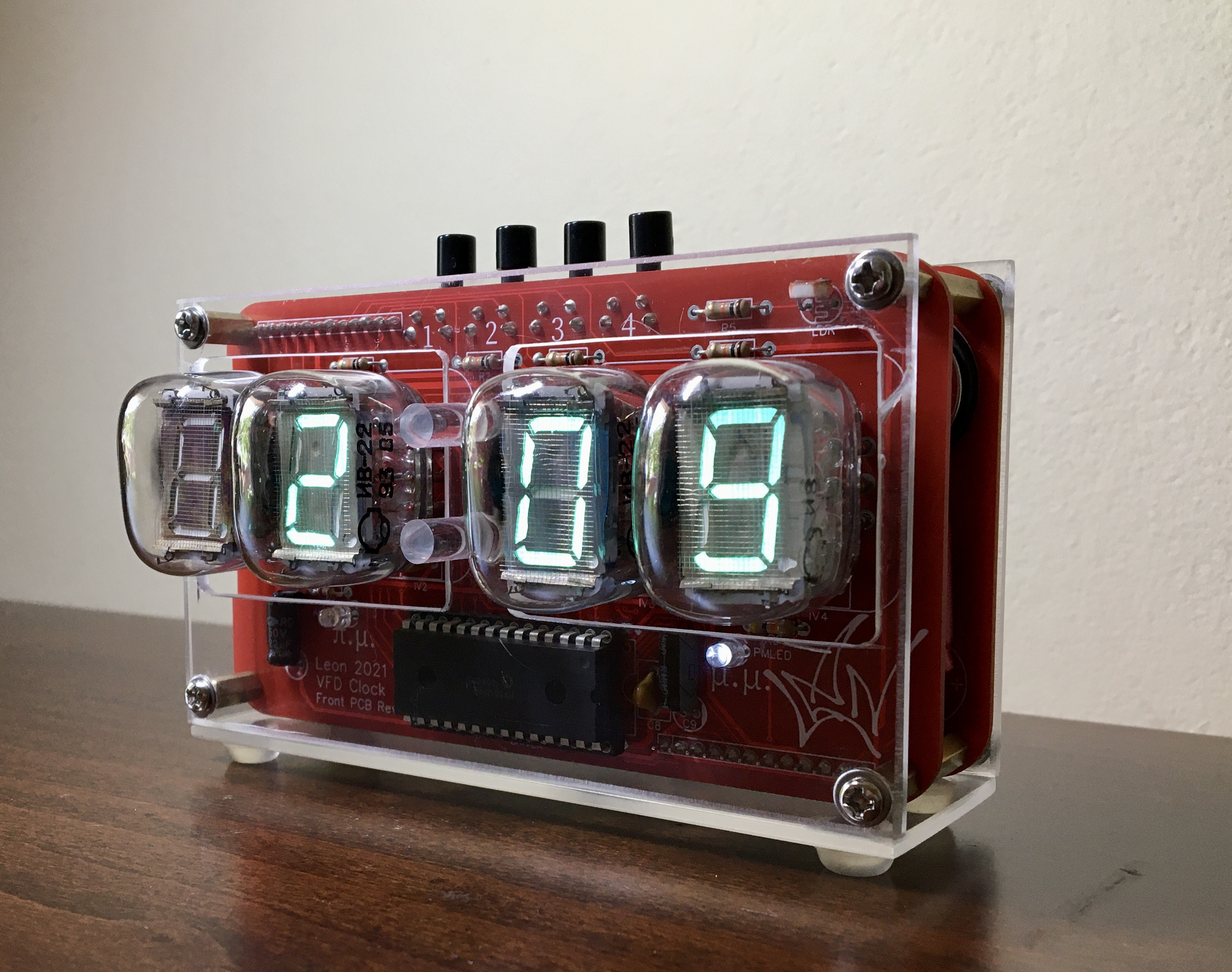
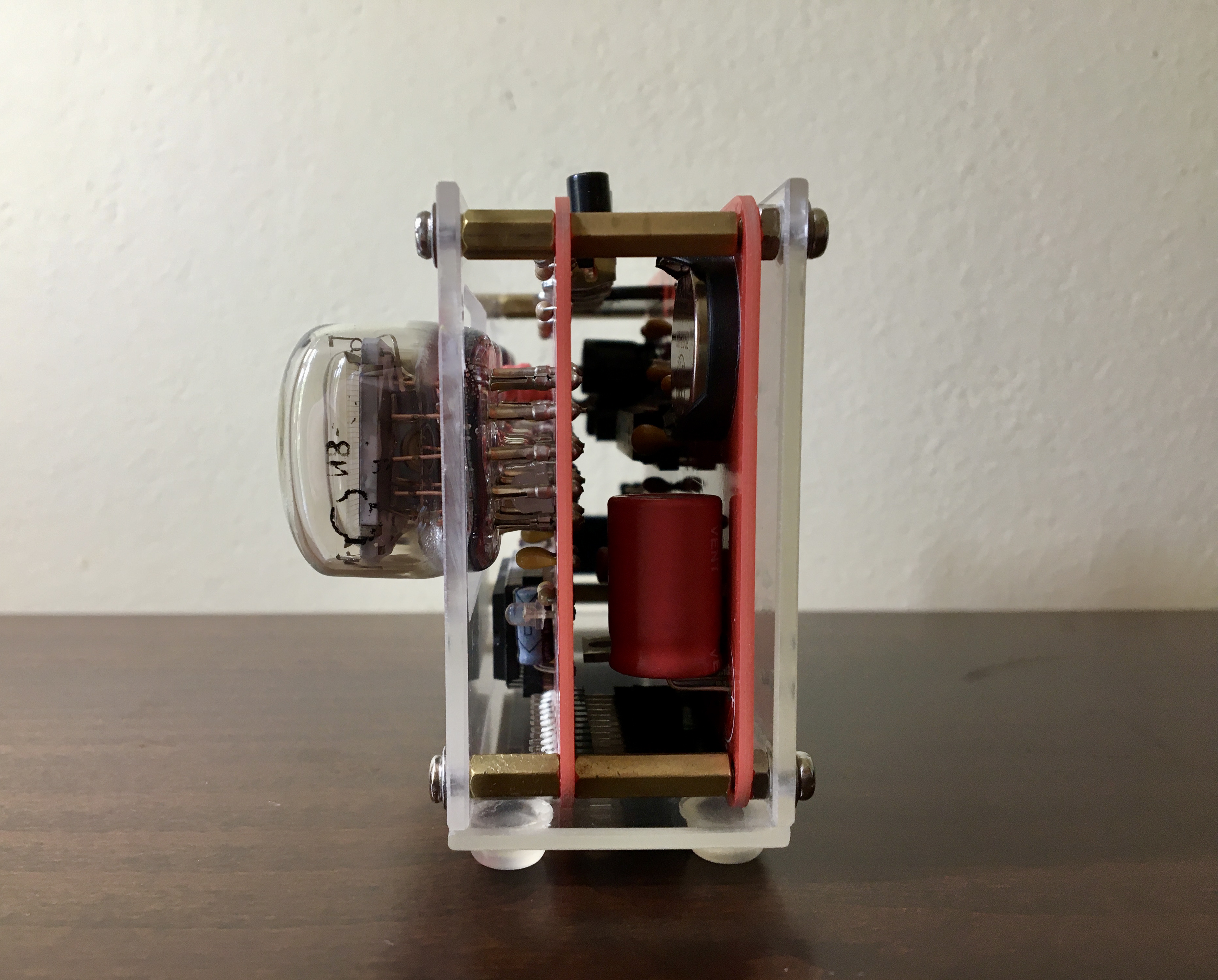
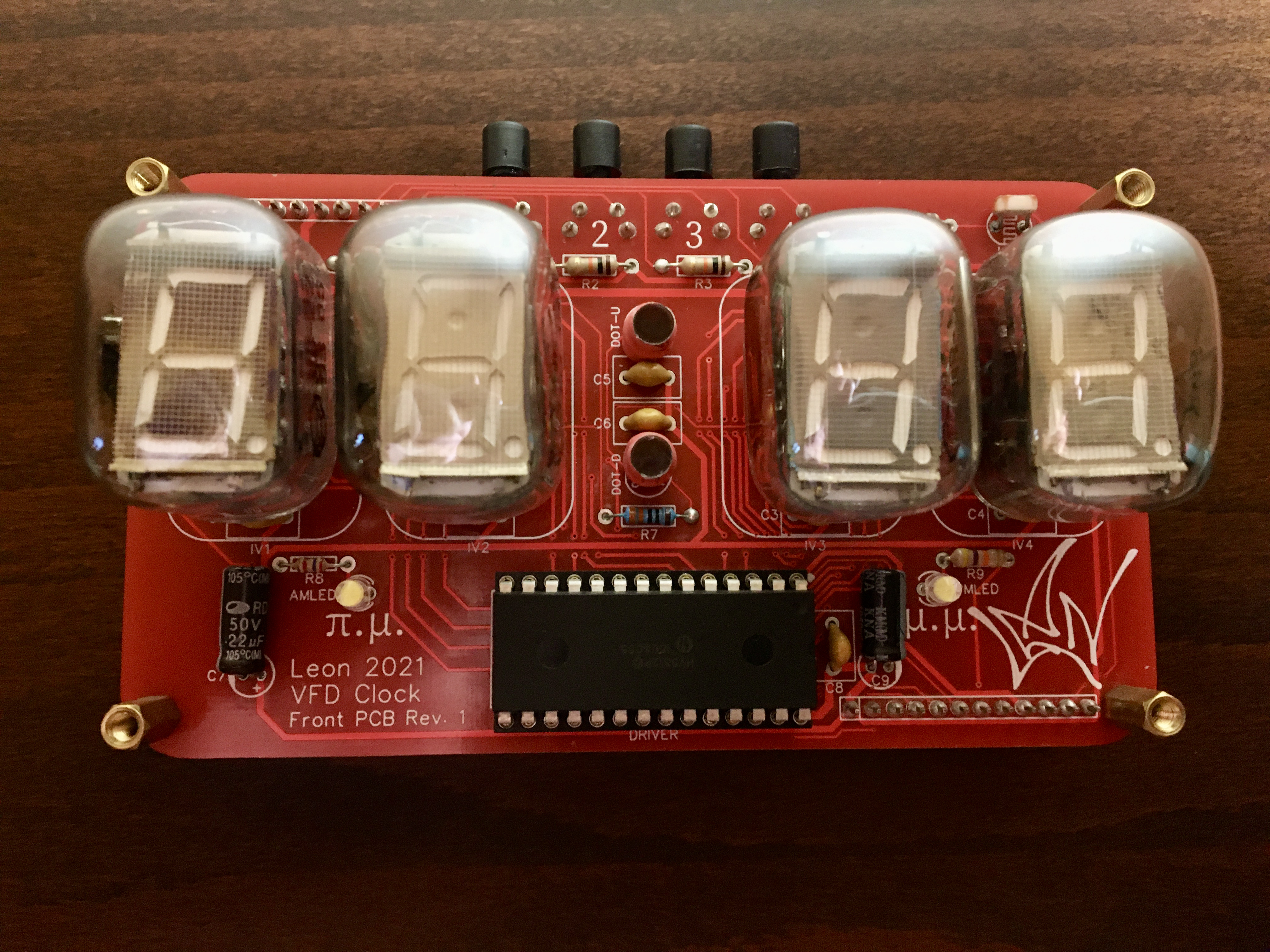
I chose the IV-22 VFD tubes because this time I wanted to use a different form factor than the IN-14 nixie tubes that I used on my previous clock. In case you are interested, you can get nixie tubes in the IV-22 form factor, they are called IN-12. Of course they are not interchangeable because they work in a completely different way but the tube has pretty much the same shape and size. All these types of tubes are not manufactured anymore but are available to buy online (ebay mostly) either used or unused from old stocks - usually referred to as NOS (New-Old Stock).
Design:
Some main considerations drove many of the design decisions:
- I wanted the component to be through hole so I can solder them hustle-free myself. That was not very easy since nowadays most of the chips are made in surface mount packages. There were times where the chip I found was perfect for the job but it was in a package that I knew would be hell to solder myself, so I skipped it. There were two components I couldn't find anything equivalent in through hole package so I had to use the surface mount. Thankfully, they both have a few pins.
- I wanted it to be relatively cheap to make because I am going to make a handful of them, not just one. Since the tubes are the most expensive component of the clock, I decided to have only four of the and skip the "seconds" of the time display.
- In order to keep costs and size down, I needed to use one VFD driver chip so I had to multiplex the tubes. Multiplexing is a technique for sending signals to multiple tubes sharing the same signal connections. The trick is that the tubes are switched on and off in order to diplay the correct number and the switching so fast that the human eye can't notice. In my case, tubes 1 and 2 share the same signal connections as well as tubes 3 and 4. So, when tube 1 displays a specific number, tube 2 is off and the opposite - you get the picture.
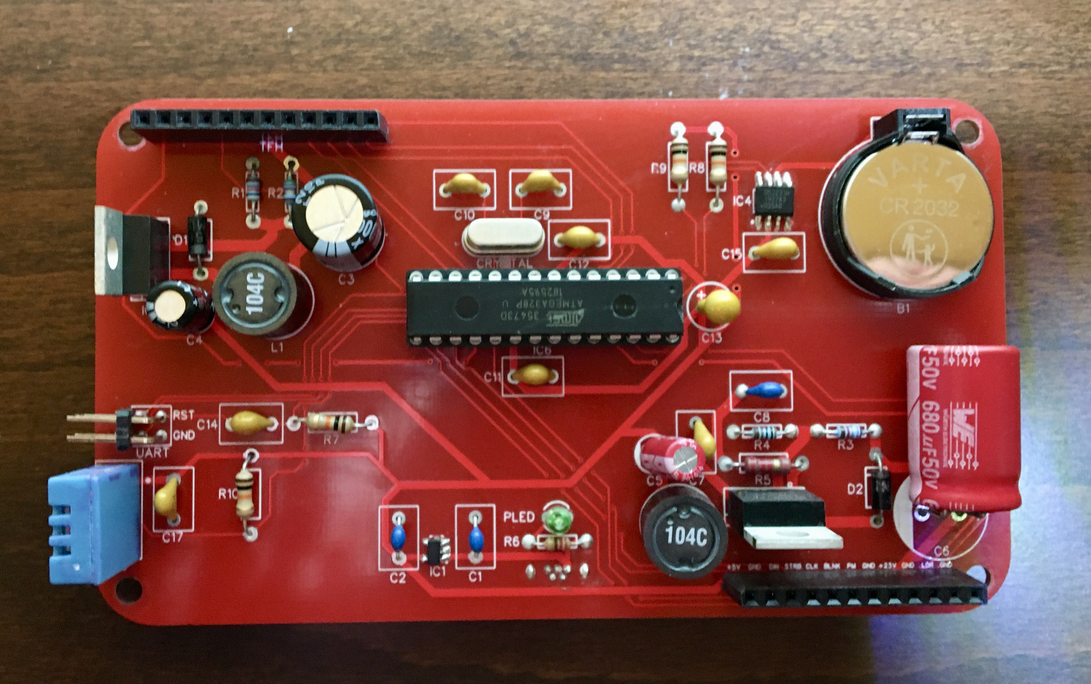
- Since all my previous projects (all three of them...) were made using Arduinos, I wanted to program this one using the Arduino IDE which I already knew. So the decision was made to utilize the microcontroller of the famous Arduino UNO, the ATMEGA328P. That way, from a software standpoint it would be like programing and Arduino UNO.
- Once the firmware is done there is no longer a need to upload regularly code to the microcontroller, so I decided to skip the UART part of the usual Arduino hardware and have just a header to connect an FTDI board and communicate through that with the Arduino IDE.
So, how is the code uploaded you may ask? It is very easy actually: you connect the FTDI board to the computer usb port and the RXD, TXD, DTR and GND pins of the FTDI to the corresponding pins of the clock which must be powered. In the the Arduino IDE select Tools-> Board:-> "Ardruino Uno". Write your code like you would for and Arduino Uno and press upload. Just remember that for this to work the ATMEGA328p microcontroller must be loaded with the Arduino Uno bootloader. You can do this yourself(therearealotofguidesonline) or you can buy the chip preloaded with the bootloader.
Features:
The clock has the following features implemented:
- Time display of course, both in 24 and 12 hour format, with blinking colon and am/pm indicator
- Accurate time keeping and battery to keep the time when the power is off
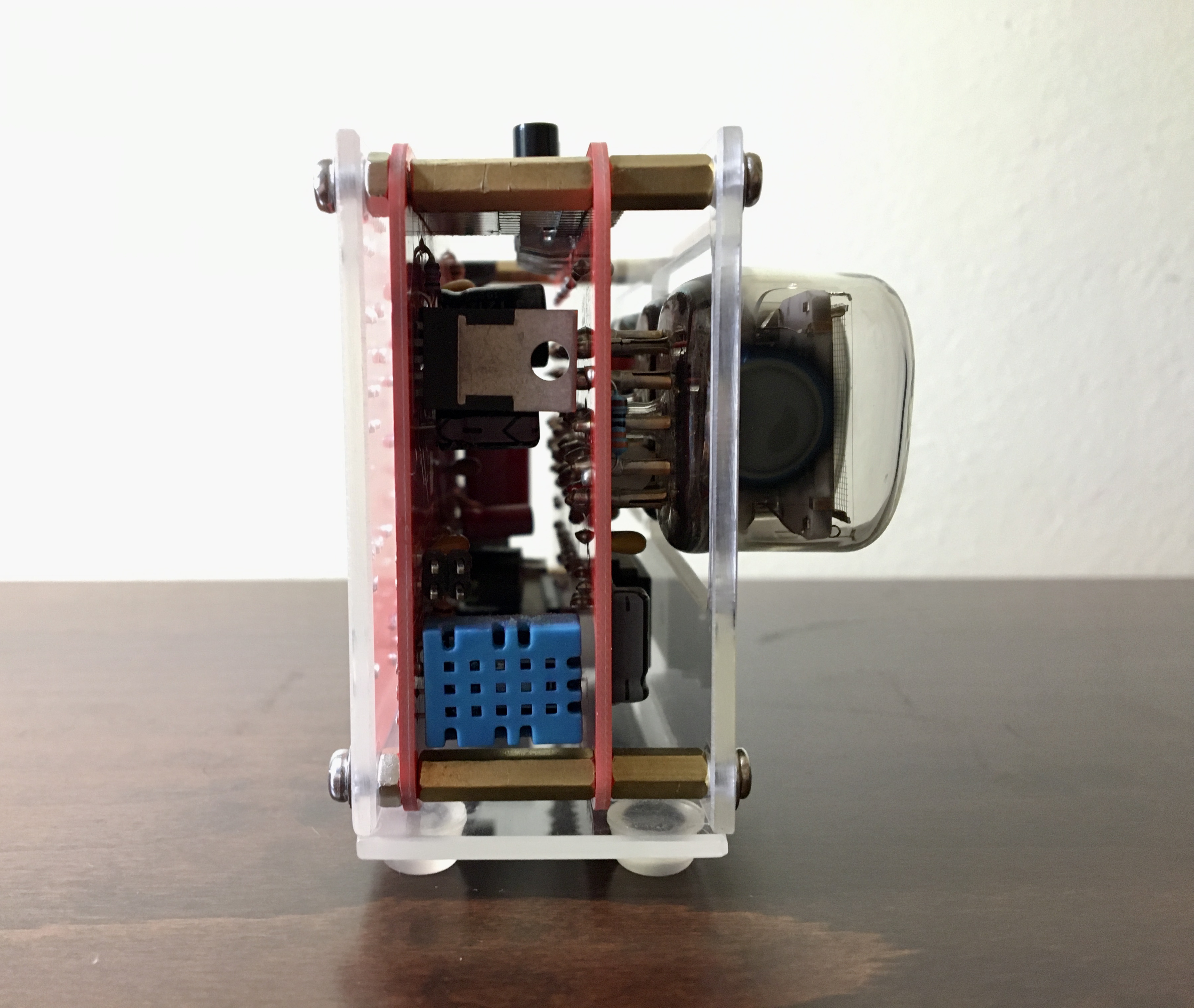
- Room temperature and humidity display
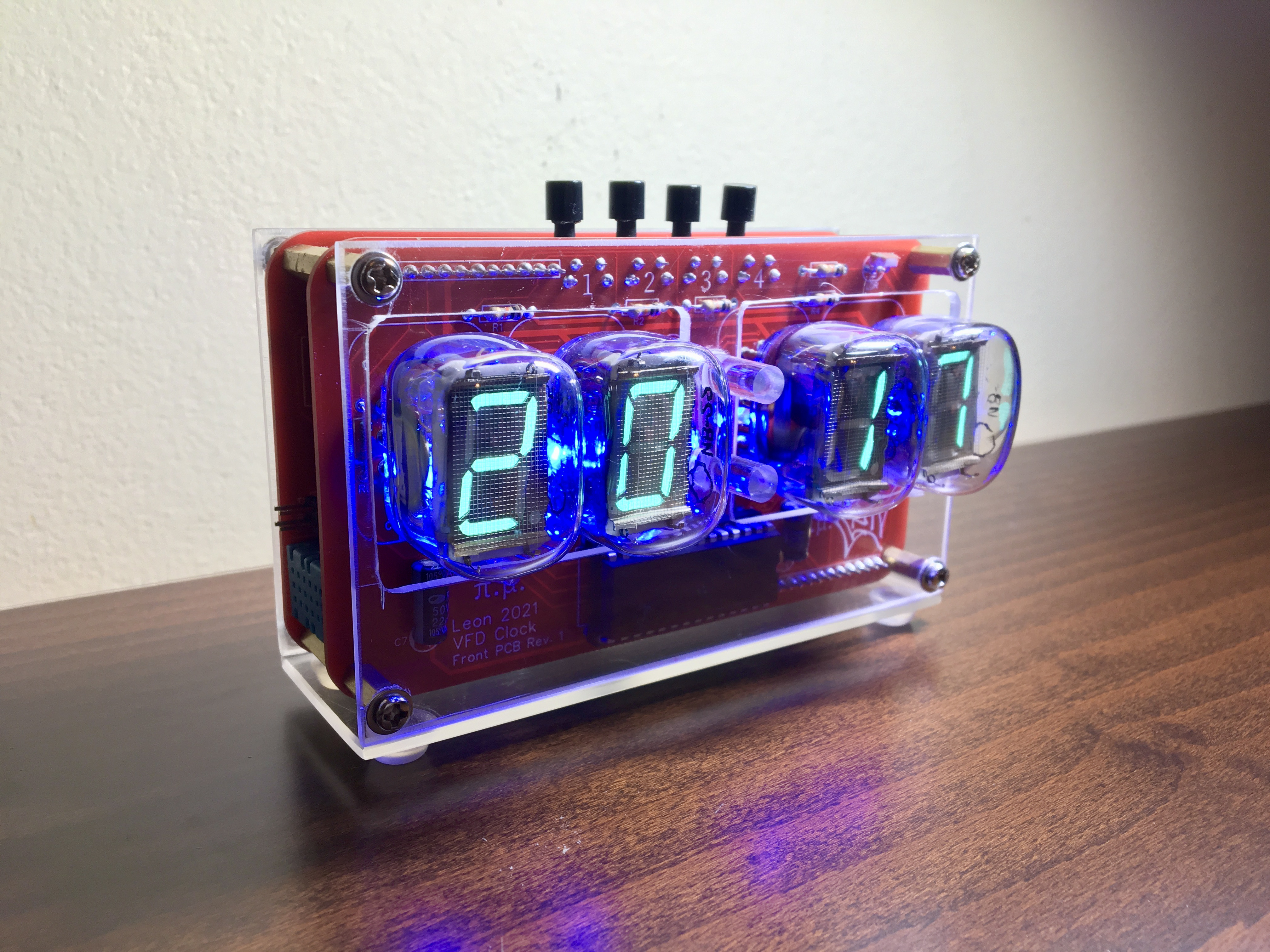
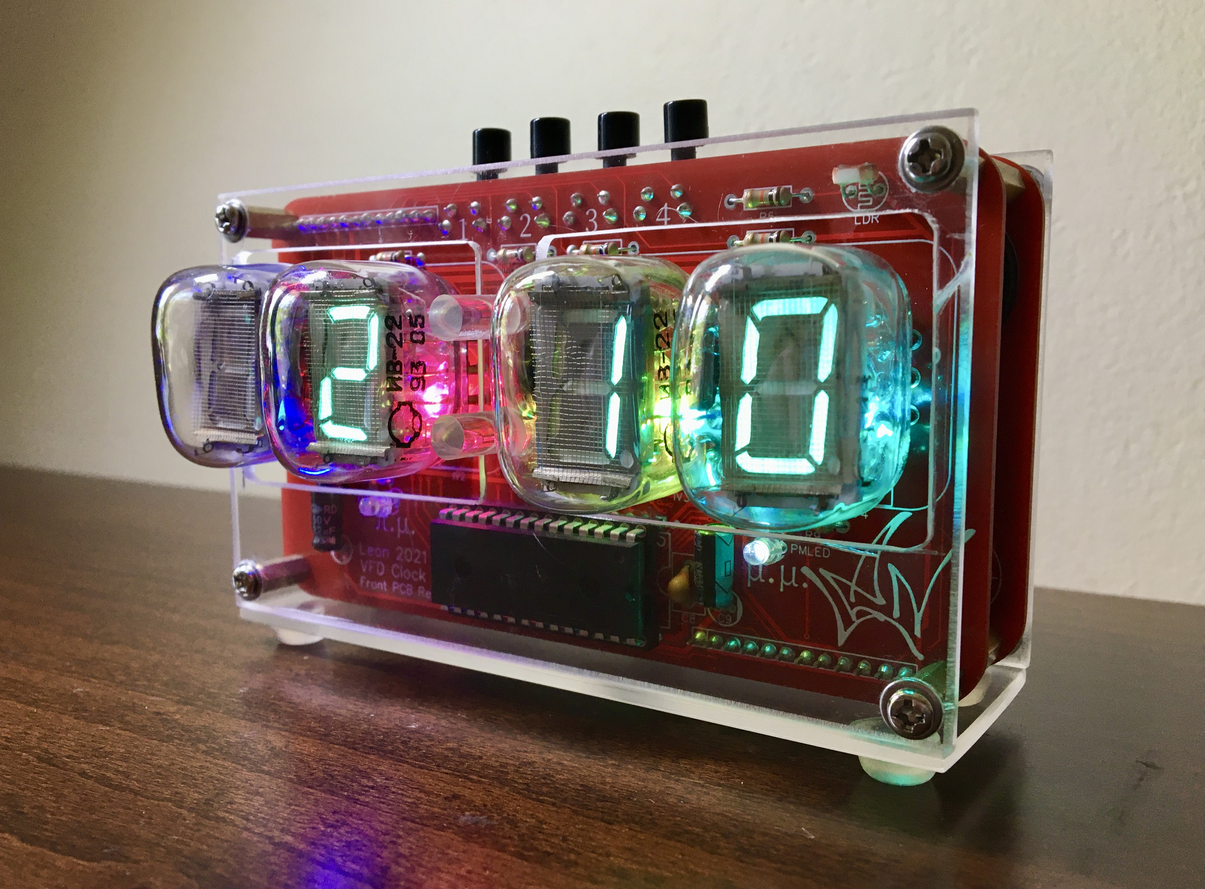
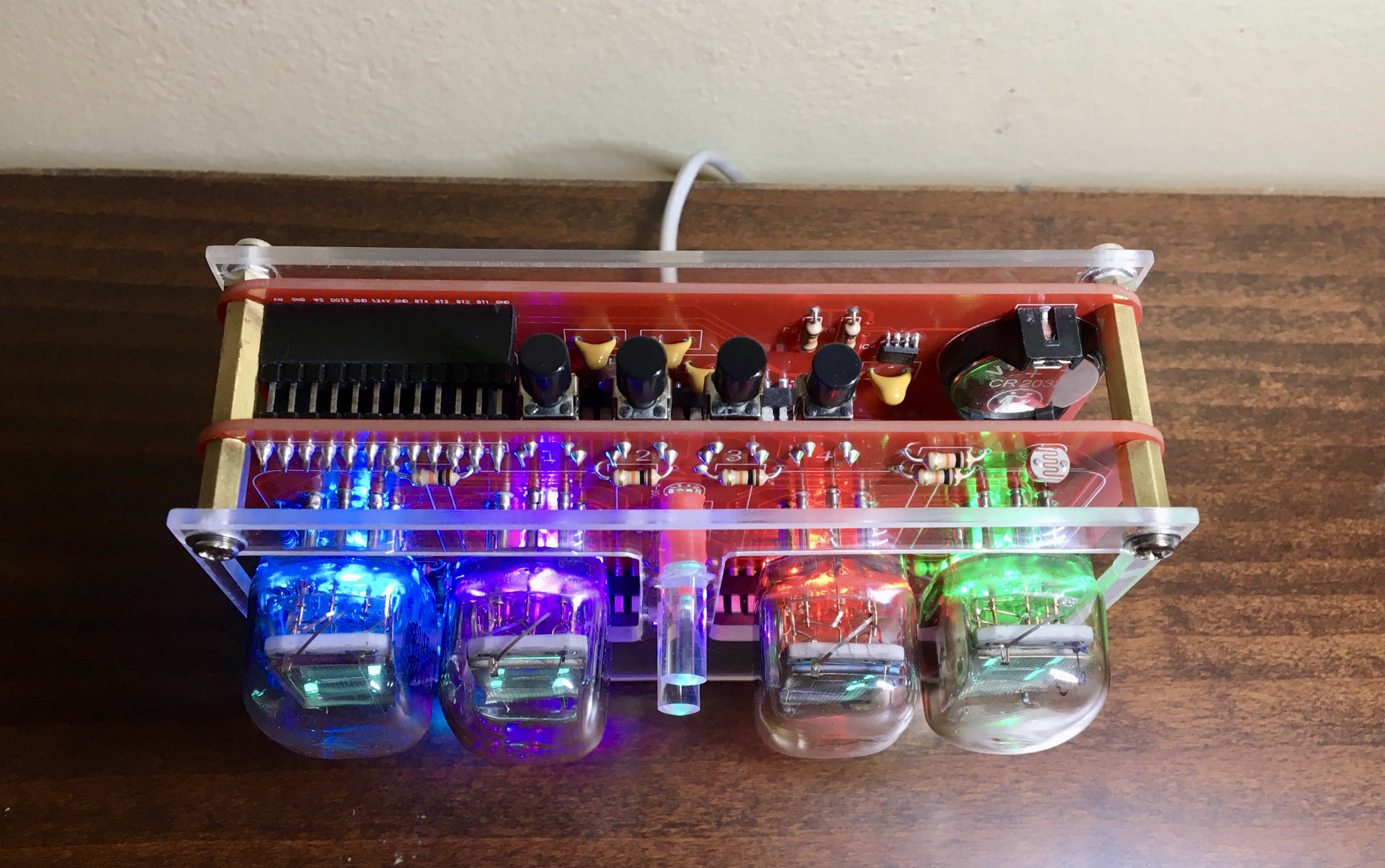
- RGB LED backlight on the tubes, with five different color effects
- Light sensor and automatic dimming of the tubes and LEDs depending on the light in the room
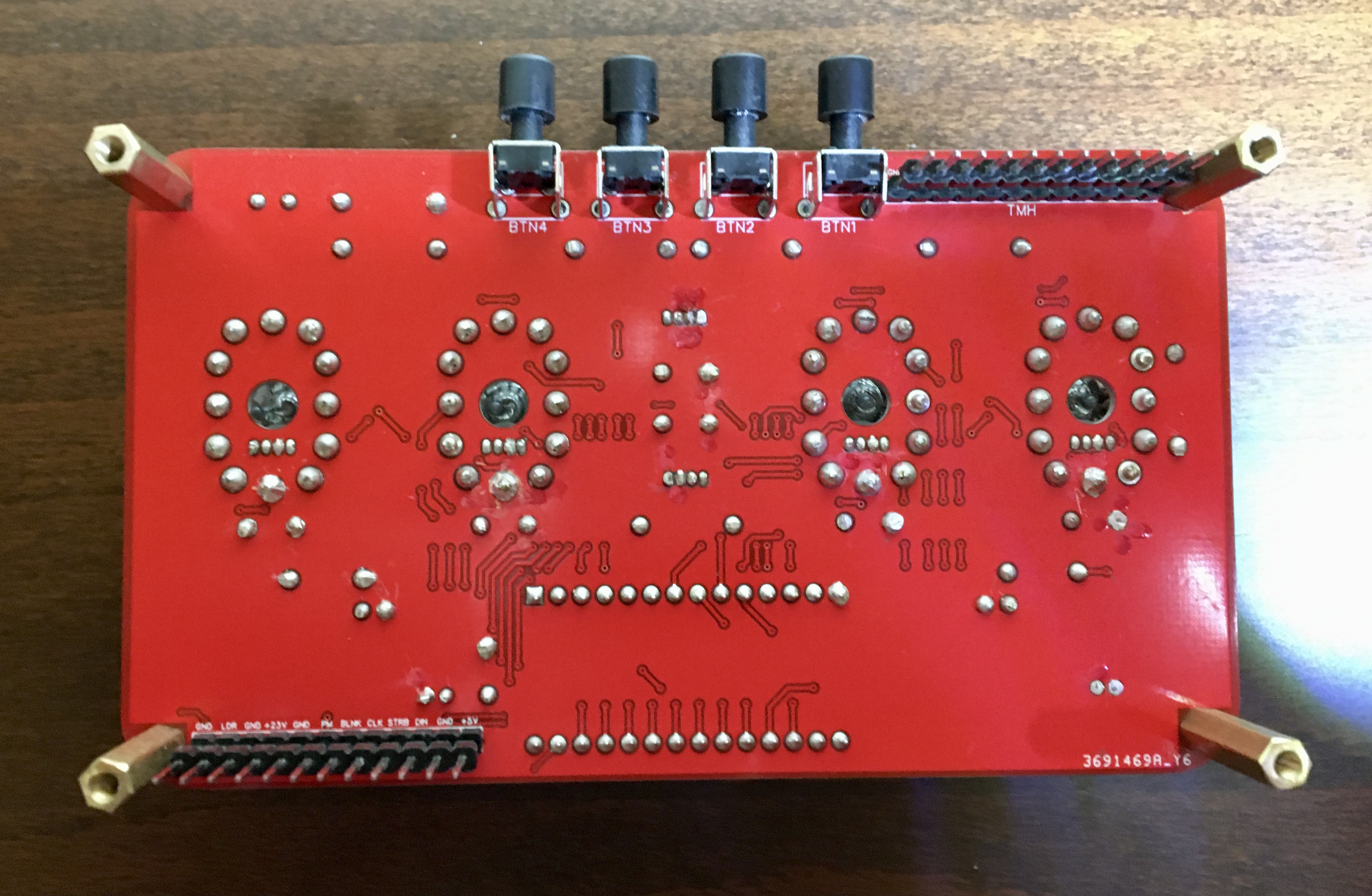
- Four buttons which can control the following:
- - set the time
- - switch modes (12hour, 24hour, temperature & humidity periodically, temperature & humidity only)
- - circle through the LED color effects
- - turn the LEDs on and off
- Less than 500mAmps power consumption so you can power it even from computer USB ports
- Overvoltage protection
- Overcurrent protection
- ESD (Electrostatic discharge) protection
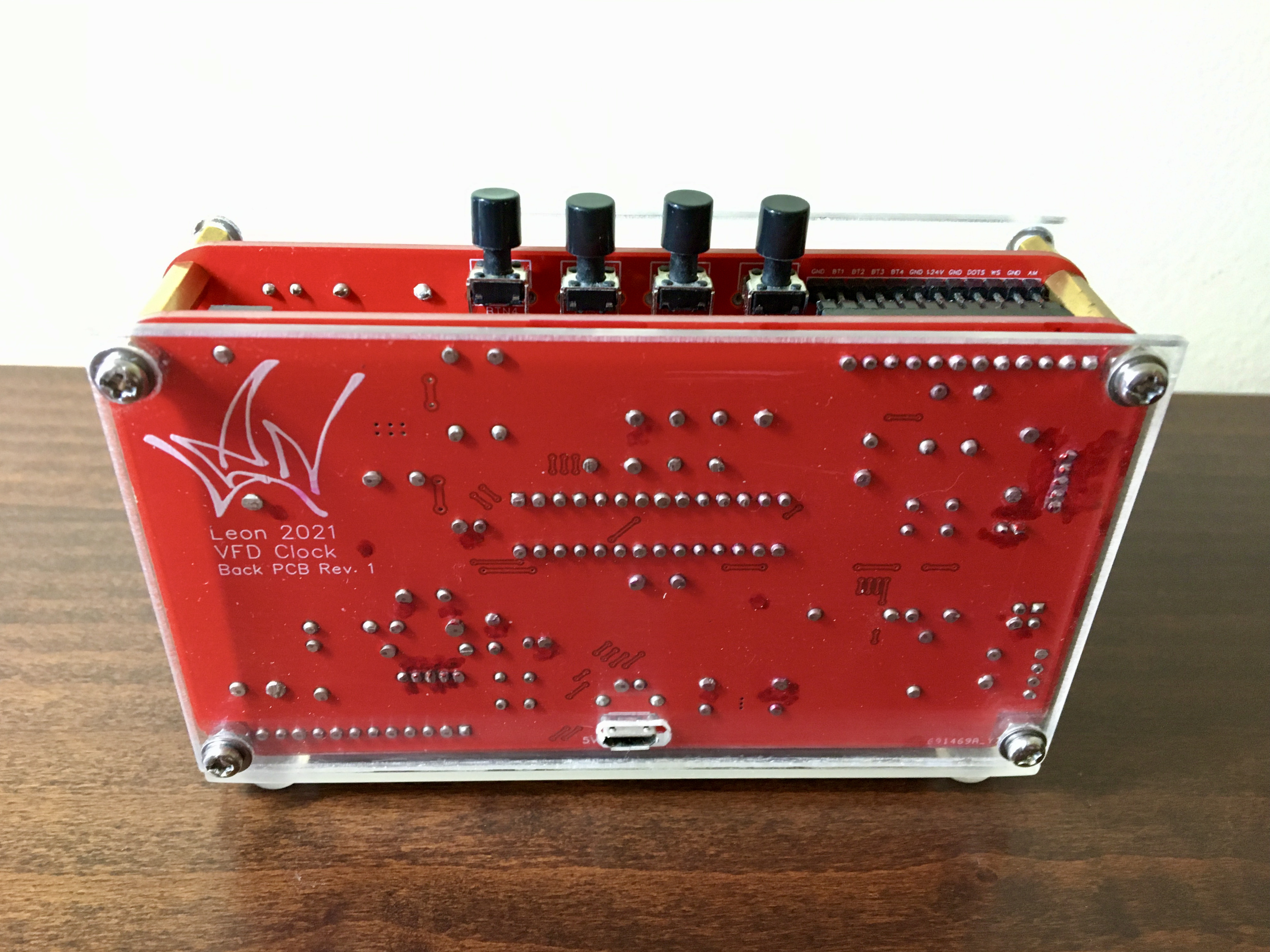
- easy access for repairs
I'm also planing to implement the following features in the firmware:
- Routine that turns the tubes and LEDs off at night when there is no light in the room to save power and increase their lifetime
- Save the settings to EEPROM in order to keep them after resets and power cutoffs
- Startup routine when you plug it in so you can see that everything is working (and to look cool)
Lessons learned:
Designing my first PCB wasn't as hard as I first thought. The software is free and the services that are available online for getting your designs printed are many and relatively cheap. I got five copies (the minimum) of each PCB from JLCPCB for about 25 Euros total, including the shipping fee.
For the do's and don'ts of two layer PCB design there are many articles and forums available online (electronics.stackexchange.com totally rules by the way), that can help you along. Also keep in mind that the data sheets of the components you choose are your best friend.
EXPANDED TECHNICAL DETAILS
Vintage Vacuum-Fluorescent Horological Hub
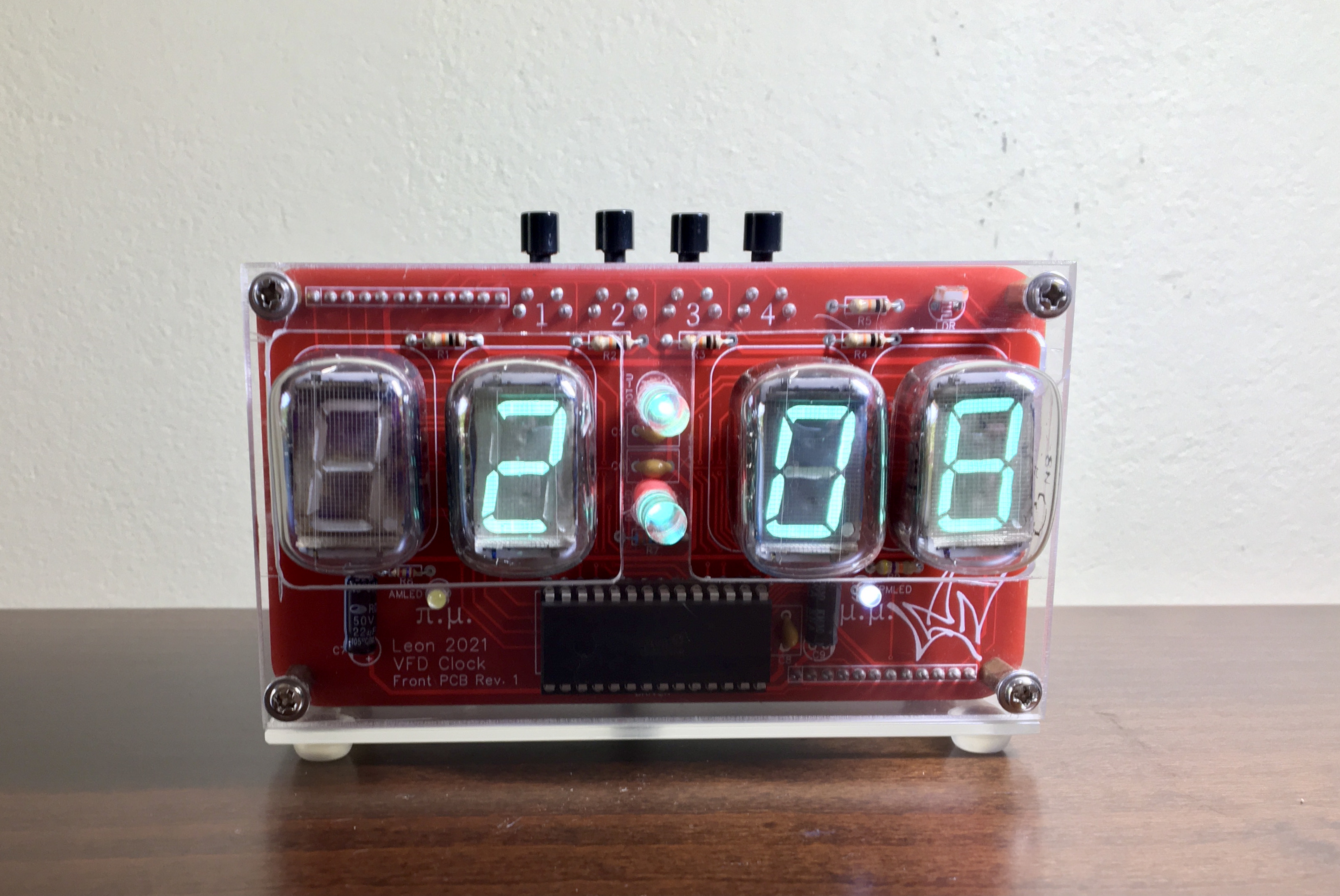
This project combines high-precision modern timekeeping with the beautiful "Cyan" glow of vintage Soviet IV-22 VFD (Vacuum Fluorescent Display) tubes.
- High-Voltage Shift-Register Matrix: The IV-22 tubes require approximately 25-30V for the anodes. The Arduino manages these high voltages through EasyEDA-designed driver boards using shift registers and transistor arrays.
- DS3231 RTC Temporal Synchronization: Uses an I2C Real-Time Clock with temperature compensation. The Arduino performs a "Drift Correction" every 24 hours to maintain accuracy within 2 minutes per year.
Design
- Verified with Arduino IDE: Optimized for 100% stable performance, with a special "Cathode-Care" routine that ensures the vintage tubes last for decades of operational life.