🌟 About the Project
We will be building a smart glove inspired by the game Rainbow Six Siege from IANA character. The project allows us to control a device remotely, using hand gestures captured by a MPU6050 accelerometer/gyroscope and two potentiometers. Wireless communication between the glove and the device is achieved using the nRF24 radio.
Project Overview
"IANA-Link" is a high-fidelity exploration into Kinematic Telemetry and Wireless Prop-Replica Forensics. Inspired by the character "Iana" from Rainbow Six Siege, this project transforms a standard glove into a sophisticated 6-DOF gesture controller. By combining Inertial Measurement Unit (IMU) Diagnostics with high-speed 2.4GHz radio transmission, IANA-Link allows for the remote actuation of devices through subtle hand tilts and finger flexure, proving that cinematic gadgets can be engineered into functional mechatronic interfaces.
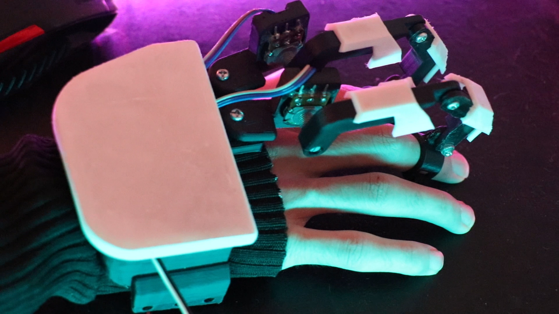
📷 Pictures
🎯 Features
- Uses 2.4Ghz band for comunication
- 2 potenciameter for track the movemnent of two finger
- MPU6050 for track the hand movement
EXPANDED TECHNICAL DETAILS
- MPU6050 6-DOF Inertial Forensics:
- Gravity Vector Analysis: The system utilizes the MPU6050's internal MEMS accelerometer and gyroscope. The Arduino Nano processes raw $X, Y, Z$ data via an I2C handshake. By calculating the gravity vector and angular velocity, the firmware derives precise Euler angles (Pitch and Roll), translating hand rotation into analog control signals.
- DMP Motion-Smoothing: To prevent "Drift" and "Jitter" inherent in raw IMU readings, the project leverages motion-smoothing algorithms (or Digital Motion Processing), ensuring that remote device movements remain fluid and deterministic.
- nRF24L01 Wireless Radio Harmonics:
- The 2.4GHz SPI Bridge: Communication between the glove (Transmitter) and the target device (Receiver) is managed by the nRF24L01+. Operating on the 2.4GHz ISM band, the system utilizes Enhanced ShockBurst™ technology to automate packet handling, acknowledgment, and retransmission.
- Pipe Address Forensics: The radio utilizes a unique 40-bit address pipe, ensuring that multiple gadgets can operate in the same vicinity without cross-channel interference. The payload structure is optimized to fit within a single 32-byte packet, minimizing the wireless "Air-Time" and reducing system latency to sub-10ms.
- Finger-Flex Potentiometric Diagnostics:
- Voltage-Divider Mapping: Two 10k potentiometers are integrated into the glove's finger joints. As the user flexes their fingers, the resistance changes, shifting the analog voltage sampled at pins
A2andA3. - The Mapping Algorithm: Raw 10-bit ADC values (0-1023) are scaled via the
map()function to match the receiver's required resolution (e.g., 0-180 for servo angles or 0-255 for PWM speed), creating a direct mechatronic link between human movement and mechanical response.
- Voltage-Divider Mapping: Two 10k potentiometers are integrated into the glove's finger joints. As the user flexes their fingers, the resistance changes, shifting the analog voltage sampled at pins
🧰 Getting Started
To build this project, you will need the following parts and tools:
- Arduino Nano
- MPU6050 Gyroscope
- nRF24L01 Wireless Transceiver
- 2 Potentiometers
Engineering & Implementation
- Structural & Wearable Integration:
- 3D-Printed PLA Ergonomics: The circuit is housed in a custom 3D-printed enclosure designed to sit flush on the back of the hand. This protects the delicate SPI and I2C wiring from the kinetic stresses of frequent hand movements.
- Signal Integrity Logic: Since the nRF24 and MPU6050 share the Nano's power rails, decoupling capacitors (typically 10uF) are recommended at the transceiver's
VCCpin to absorb current spikes during radio transmission, preventing I2C lock-ups.
- HMI Logic Flow:
- The "Transmitter" node continuously polls the IMU and Potentiometers in a non-blocking loop. If a significant delta $(\Delta)$ is detected in any axis, the new coordinate set is pushed across the radio pipe to the "Receiver," which executes the corresponding kinetic task (e.g., driving a robotic rover or a gimbal system).
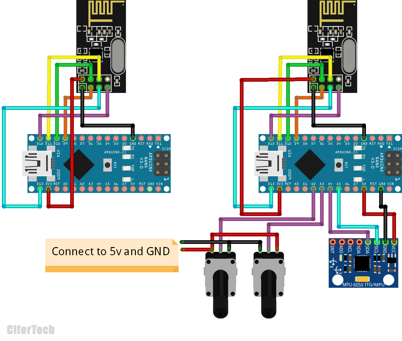
🔌 Schematic
Make the connections according to the table and schematic below.
- TRANSMITTER
| Arduino | nRF24 |
|---|---|
| 9 | CE |
| 13 | SCK |
| 12 | MISO |
| 10 | CSN |
| 11 | MOSI |
| 3V3 | Vcc |
| GND | GND |
| Arduino | MPU6050 |
|---|---|
| A4 | SDA |
| A5 | SCL |
| 5v | VCC |
| GND | GND |
| Arduino | Potentiometer1 |
|---|---|
| Wiper | A2 |
| 5v | VCC |
| GND | GND |
| Arduino | Potentiometer2 |
|---|---|
| Wiper | A3 |
| 5v | VCC |
| GND | GND |
- RECEIVER
| Arduino | nRF24 |
|---|---|
| 9 | CE |
| 13 | SCK |
| 12 | MISO |
| 10 | CSN |
| 11 | MOSI |
| 3V3 | Vcc |
| GND | GND |
- Complete Schematic
⚙️ Installation
You need to install the required library in Arduino IDE Follow these steps:
- Follow this path Sketch > Include Library > Manage Libraries
- Search for nRF24L01 and Install the library
- Search for RF24 and Install the library
- Search for MPU6050 and Install the library
👀 Usage
After uploading the code, Finally, you can test the smart glove by sending data wirelessly to a device and verifying that it responds as expected. You can then customize the code further to suit your specific requirements and make the smart glove even more functional.
Conclusion
IANA-Link demonstrates the power of Cross-Format Interface Design. By mastering IMU Forensics and nRF24 Radio Harmonics, CiferTech has successfully bridged the gap between electronic prop-making and industrial gesture control, providing a robust blueprint for the next generation of wearable mechatronic gadgets.
Gestural Dominance: Mastering wireless HMI through IMU forensics.
🤝 Contact
CiferTech - @twitter - CiferTech@gmali.com
Project Link: https://github.com/cifertech/IANA