I2C Multiplexing: Dual 16x2 LCD Panel Architecture
Introduction
In this project, I will show you how to connect two LCDs together using only an Arduino. When I started this project, I faced many difficulties, so I will share how you can make this project easily without any trouble. I searched a lot about this project on the internet but could not find any helpful information.
About the Device
When you connect two LCDs together with an Arduino, the text that finishes scrolling on one LCD will automatically transfer to the other. I had a lot of trouble figuring out the Arduino coding for this. A standard 16x2 LCD display connected to an Arduino Nano uses 12 pins. Therefore, connecting two 16x2 LCD displays would typically require 24 pins, with 6 pins per display used for data transfer. In my setup, I only connected 14 pins from the LCDs to the Arduino Nano: 12 pins for data transfer and 2 pins for other functions.
However, there is a much more efficient method than using all those pins. If an engineer needs extensive text telemetry (like tracking a spaceship game or displaying multiple rows of statistics), a single 16x2 LCD is fundamentally inadequate. The obvious solution is to add another display! However, connecting two LCDs using the standard I2C protocol presents an immediate problem: they typically share the exact same hardware address (usually 0x27). When the Arduino sends a command to display "HELLO," both screens would show "HELLO" simultaneously. To solve this, you must physically modify the hardware on the I2C backpacks to create independent addressing for each screen on the same data bus!
The Physical I2C Address Solder-Bridge (PCF8574)
The raw SDA (data) and SCL (clock) pins can be connected in parallel to both screens safely. The core issue is the I2C device ID code.
- The black PCF8574T chip on the back of the LCD module has three tiny solder pads labeled
A0,A1, andA2. - By default, these are left disconnected (open), resulting in the default address
0x27. - To give the second screen a unique ID, use a soldering iron to bridge the
A0pad on only one of the displays. - This hardware modification changes that LCD's address to
0x26.
Here is the fundamental code structure to control both displays independently:
#include <LiquidCrystal_I2C.h>

// Initialize each LCD with its unique I2C address
LiquidCrystal_I2C lcd1(0x27, 16, 2); // The default, unmodified LCD
LiquidCrystal_I2C lcd2(0x26, 16, 2); // The LCD with the soldered A0 bridge

void setup() {
  lcd1.init();
  lcd2.init();

  lcd1.backlight();
  lcd2.backlight();

  lcd1.setCursor(0, 0);
  lcd1.print("Master Control!");
  lcd2.setCursor(0, 0);
  lcd2.print("Telemetry Hub!"); // Each screen operates independently!
}
Eliminating the 16-Wire Ribbon Cable Nightmare
Before I2C backpacks were common, connecting two bare LCD screens required a complex maze of up to 12 wires per display, exhausting nearly all digital pins on an Arduino Uno.
- By utilizing the
I2Cprotocol, the Arduino only uses two pins: Analog 4 (SDA) and Analog 5 (SCL)! - You can theoretically connect up to eight (8) LCDs to these same two wires, provided you assign a unique solder bridge configuration (using combinations of
A0,A1,A2) to each module.
Required Components
- Arduino Uno/Nano (Handles the central logic and string parsing).
- Two 16x2 Character LCD Screens with
I2C PCF8574 Backpack Modules. - A fine-tipped Soldering Iron and Solder (Mandatory for bridging the address pads).
- I2C Scanner Sketch (A crucial troubleshooting tool that scans the bus to verify the addresses have successfully changed to
0x27and0x26).
Demo Video
{% embed url="https://www.youtube.com/embed/YRgJcx0-wZY" %} Project demo video about how it works {% endembed %}
Please like, share, comment, and subscribe.
Project Images
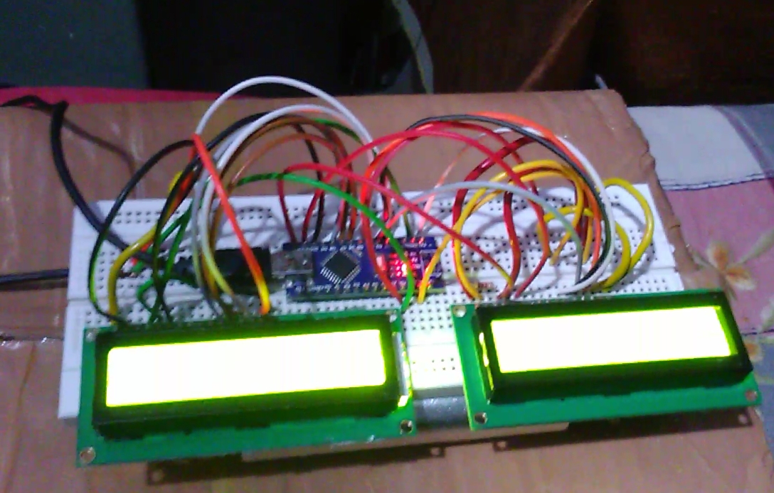
Image of project
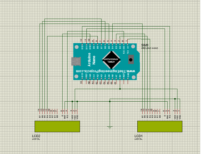
Circuit Diagram