During the demonstration, keep calm and leave sufficient breaks between movements, especially when reset times are necessary as you will see below. How does it work?
1. Whenever the device is powered, (always with the switches in the "off" position), it starts in the learning sequence, starting from LED 1. Place the colored cards in any order you want. One color for the LEDs and one for the switches.
Turn on the switches starting from LED color 1 in order up to LED 4. Turn on the corresponding color switch from LED no.1. For example, if led no. 1 has a red card, turn on the switch with the same color first. Next is the color from led no. 2, we turn on the switch with the same color. Then in order 3, 4, following the colors. It is always learned starting from led no.1...4. At this moment the buttons are "learned"and each one will light up in correspondence with the corresponding colored card, and you can turn them off or on in any order you want. If switch No. 1 is switched last to the "off" position and is held in this position for 3 seconds or more, the device enters the learning process again.Move the cards in any order you want, the learning process begins again, and the spectators will be amazed how the lights turn on in a different order.For a successful show, move the cards to the LEDs and to the switches, ask one of the spectators to place them in any order they want. You will be amazed to see how each color on the switch will turn on the corresponding light of the switch color, changing the order.Amazing, right?
Before moving on to trick no. 2, turn off switch no. 3, the last one, and wait 3 seconds or more. Let's go to trick no. 2
2. If switch no.3 is turned off last and is kept in the off position for 3 seconds or more, the device goes to trick number no.2. Keep any of the switches off for 4 seconds or more and it becomes inactive. Switch back to the off position and wait 4 seconds or more, it becomes active again. Attention: at this moment of the demonstration, at least one of the switches must be in the "on" position
Turn the switches on and off a few times. Leave one of them, any one, in the "off" position and the other 3 in the "on" position. Wait 4 seconds or more, during this time remove the colored cardboard either from the switch or from the corresponding color LED. Put the switch in the on position, and the LED will stop lighting up. Spectators will see that if the color is missing, the LED does not light up. Amazing, right? Let's move on: put the switch in the "off" position again, wait 4 seconds or more, during which you talk to the spectators and put the colored cardboard back. Turn on the switch and amazingly, the light will come back on! The effect is maximum! Practice until you turn off 3 of the lights, turning off the switches in turn and removing the colored cards.
Turn the last switch to the "off" position. Remove the colored cardboard. At this moment, none of the LEDs will light up. Turn all the switches to the "on" position and move on to trick no. 3!
3. Turn all 4 switches to the "off" position, wait 5 seconds and the device locks in sequence 1234. You can light the LEDs in any order you want, but only with the switch assigned in front of it, during which you place the colored cards of the LEDs and switches in the same order. The color of led no.1 should be the same as that of switch no.1, the color of led no.2, the same as that of switch no.2, ....and so on until led no.4
!!! At this moment you can hand the device to the audience you are giving the demonstration to. It is blocked and can no longer enter any programming sequence and behaves normally like a classic circuit.
4. To unlock, you can remove the battery or turn switch no. 2, 5 times or more consecutively from the off/on position. The other switch must be in the off position. At this moment, the device is active again in switch learning positions.
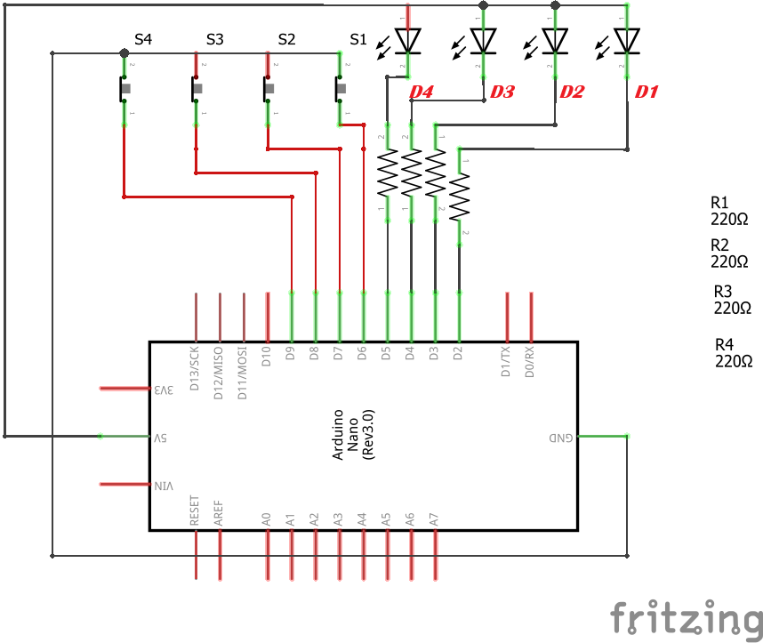
Schematic Diagram:
The electrical diagram is extremely simple and requires no explanation. Power the Arduino board on the Vin pin with a 6...12 volt battery.
Observe the order of the LEDs and switches.
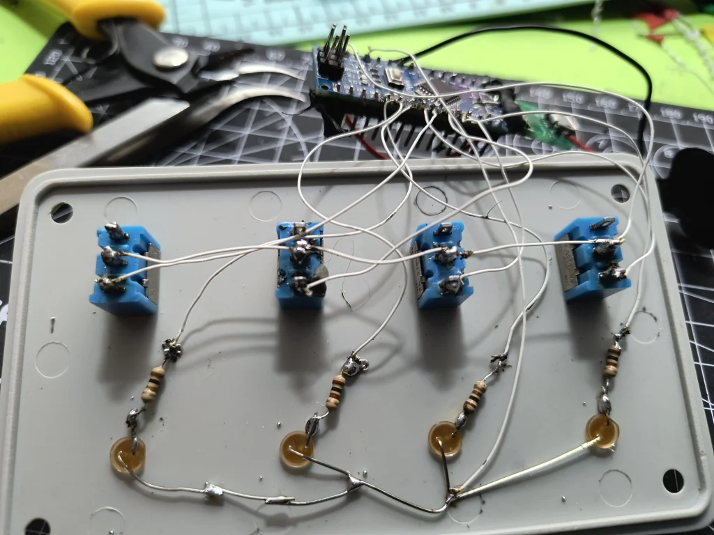
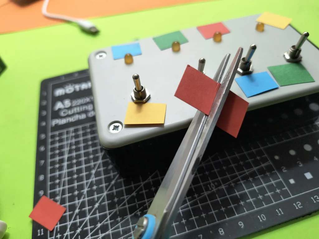
Mechanical Construction
I assembled everything in a plastic box, drilled holes for the 4 LEDs and the 4 switches. Obviously, you have to hide the contents of the box from the audience. You can choose any other version, you can replace the LEDs with bulbs that you can color and you can move them from the sockets instead of moving the colored papers. Initially, I used colored shrink tubes mounted on the switch lever, but they came out very hard, so I chose the version with colored paper.


EXPANDED TECHNICAL DETAILS
This project, often categorized under "Comedic Engineering" or "Useless Machines," is an animatronic gag that relies on precise microswitch inputs and state-based logic. The magic isn't in solving a problem but in creating a surprising and humorous interaction.
The Core Logic & Hidden Mechanism
The Arduino acts as the brain, constantly monitoring the state of the four toggle switches. It doesn't just react to an ON/OFF signal; it tracks sequences, timing, and the order of operations to determine which "trick" mode to activate.
- State Machine Design: The code is built around a state machine. It exists in distinct states (e.g., "Learning Mode," "Trick 2 Mode," "Locked Mode"). Transitions between these states are triggered by specific sequences of switch flips and timed holds, as detailed in the instructions above.
- Input Conditioning: The Arduino uses debouncing routines to ensure that the mechanical flicker of a switch being toggled is read as a single, clean press. The
millis()function is used for all timing operations (3-second hold, 4-second wait, 5-second lock), making the behavior non-blocking and reliable. - Output Control: The LEDs are driven from the Arduino's digital pins, likely through current-limiting resistors as shown in the schematic. The logic determines which LED corresponds to which switch based on the learned or locked configuration.
Adding "Personality" to the Code
While this specific box uses LEDs, the principle of adding unpredictable personality is a hallmark of comedic machines. This can be achieved through the random() function and more complex servo control. Imagine a version where:
- Reaction 1: The corresponding LED lights up immediately.
- Reaction 2: The LED blinks hesitantly a few times before staying on.
- Reaction 3: All LEDs flash in sequence before the correct one lights up.
- Reaction 4: A small servo inside the box taps on the lid impatiently before the LED turns on.
Components & Construction Notes
- Arduino Nano: Its small size is perfect for hiding inside an enclosure.
- Toggle Switches (x4): SPDT (Single Pole, Double Throw) switches are used to provide a clear ON/OFF signal.
- LEDs (x4) with Resistors: Current-limiting resistors (e.g., 220Ω) are essential to protect both the LEDs and the Arduino pins, as visible in the schematic.
- Power Supply: A 6...12V battery connected to the Vin pin allows the onboard regulator to provide stable 5V to the circuit.
- Enclosure: As shown in the construction images, a plastic or wooden box is used to hide the electronics, selling the "magic" effect. Drilling clean holes for the switches and LEDs is crucial for a professional look.
The code utilizes a lot of digital components, timers, flip flops, logic gates, and counters. These code components in Visuino or the equivalent functions in Arduino IDE (like millis(), digitalRead(), and digitalWrite()) print the methodology for presenting the 4 tricks of the magic box.
The code is compiled in the Visuino program, but you can find the code in Arduino IDE format as well as Visuino in the attachment. If you use the Arduino IDE, copy the "Mitov" folder to the Arduino libraries folder on your computer. Find the link for bookstores below.
The code has a lot of digital components, timers, flip flops, logic gates, counters. These code components print the methodology for presenting the 4 tricks of the magic box.
Load the code into Visuino or Arduino IDE, choose the correct port and load it into the Arduino board
Find all the files needed for the project in the link:https://app.box.com/s/pr8lmc4atj1pcmxd332pwrka6papuw4v
If you have any questions, you can ask them in the comments section. Watch the video for an easier understanding of the operating principle!!!