I started studying how to configure Ignition SCADA for a project at work and I wanted to have a real source of data to work with before the project starts. Ignition includes a PLC simulator but I found that un-exciting. So I decided to see if Ignition could interface with an Arduino and the result was a resounding yes.
This project, the "Industrial Nexus," is a bridge between accessible embedded hardware and enterprise-level SCADA (Supervisory Control and Data Acquisition) systems. By utilizing the Arduino MKR WiFi 1010 as a Modbus TCP Gateway, it demonstrates how to feed real-time sensor data into Inductive Automation’s Ignition platform. It replaces static simulators with live telemetry, allowing for the remote control of high-power hardware like Variable Frequency Drives (VFDs) over a secure industrial network.
This project will show you how to connect a MKR WiFi 1010 + MKR RS 485 Shield to Ignition using the Modbus driver in Ignition. A VFD is shown in this example but if you don't have a VFD you can remove that part from the code and just work with the other data which is: on-board RGB LED, push button, temp sensor, and potentiometer.
The base of the code is the example Modbus TCP server and my VFD control example which is build of off the Modbus RTU client example provided in Arduino IDE if you have the Modbus library installed.
Technical Deep-Dive
The key functions of the code are as follows:
- Set the board to be a Modbus TCP server (slave) for Ignition: The MKR WiFi 1010 acts as a server on the local network, listening for requests from Ignition. It exposes its internal memory registers over WiFi, allowing the SCADA system to read sensor values and write control commands.
- Set the board to be a Modbus RTU Client (master) for the VFD: Simultaneously, the MKR 485 Shield allows the Arduino to act as a master on a local RS485 serial bus. It polls slave devices (like a VFD) using the differential signal lines (A and B), translating their industrial data into TCP packets for the SCADA host.
- Acquire local data from a potentiometer, push button, and temp sensor: Local analog sensors are sampled via the Arduino's 10-bit ADC. To reduce network noise, the firmware can implement simple Low-Pass Filtering or "Deadband" logic before updating the Modbus Holding Registers, ensuring only meaningful changes are transmitted to the SCADA historian.
If you're not familiar with Modbus, one phrase that's always helped me understand it is "shared" addresses. For example in this case Ignition can write a "1" or "0" to a memory address in the board. Then in order to know if the VFD should run, the code takes whatever is in that memory address and writes it to another shared address in the VFD. If this value is always "0" the drive stays stopped, but once a "1" is written the drive starts to move given other parameters such as desired frequency are correct.
Engineering & Implementation
- Memory Mapping & Register Logic:
- Coils (Single Bit): Used for binary states like "Motor Start/Stop" or "LED On/Off." These are stored in the 0xxxx address range.
- Holding Registers (16-bit): Used for analog data such as temperature, potentiometer position, or VFD frequency setpoints. These are stored in the 4xxxx address range.
- Radix Addressing: Ignition requires precise configuration of the "Radix" (base-16 for hex) to ensure that the memory offsets in the code match the software tags.
- Hardware Pin Constraints: One thing to be mindful of is that pins A5 and A6 are used for controlling the RS 485 Shield RE/DE so they cannot be used for anything else. These pins are hard-wired to manage the half-duplex nature of RS485; attempting to use them for analog sensors will result in bus collisions and firmware crashes. I spent a few hours struggling with that so hopefully if you're trying to replicate this you have read this section!
- VFD Control Logic: The Arduino parses "Start/Stop" bits from the SCADA Coil and immediately initiates a Modbus RTU write to the VFD’s control register. This "Bridge Pattern" ensures that high-voltage industrial equipment remains isolated from the browser-based UI while maintaining real-time responsiveness.
Ignition is really great because you can download it and start learning for free. Below are some key things you need to know in order to configure the device section of Ignition.
When you first boot up your board, get the IP address using serial monitor.
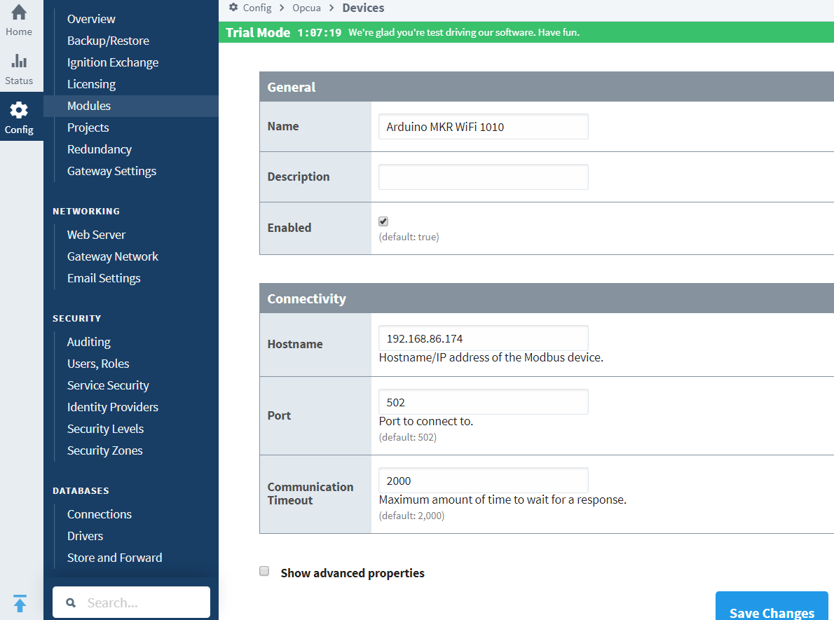
Of course your board and Ignition instance must be on compatible IP addresses (i.e. you can do CMD --> ping 192.168..xx.xxx and get a reply).
Network & Security Layer:
- TCP/IP Handshaking: The MKR WiFi 1010 requires a static or reserved IP to ensure Ignition doesn't lose connection. The communication happens over Port 502 (Standard Modbus) or custom ports like 8088 for the Ignition Gateway.
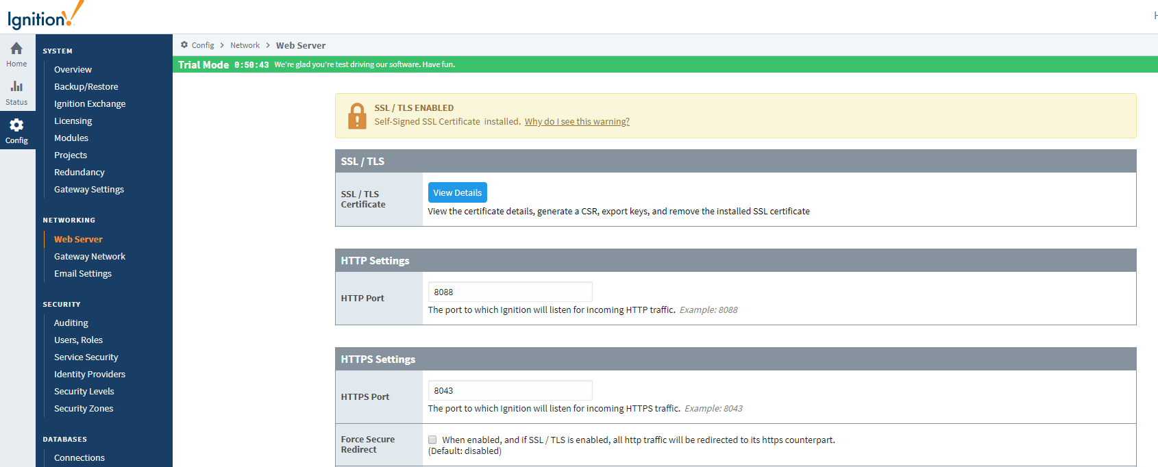
- SSL/TLS & Firewall Management: For professional deployment, the guide covers enabling Self-Signed SSL Certificates and managing inbound/outbound rules to protect the SCADA gateway from unauthorized network access.
Enter the addresses. Key point is that hex addresses (i.e. 0x01) require the "Radix" setting be 16.
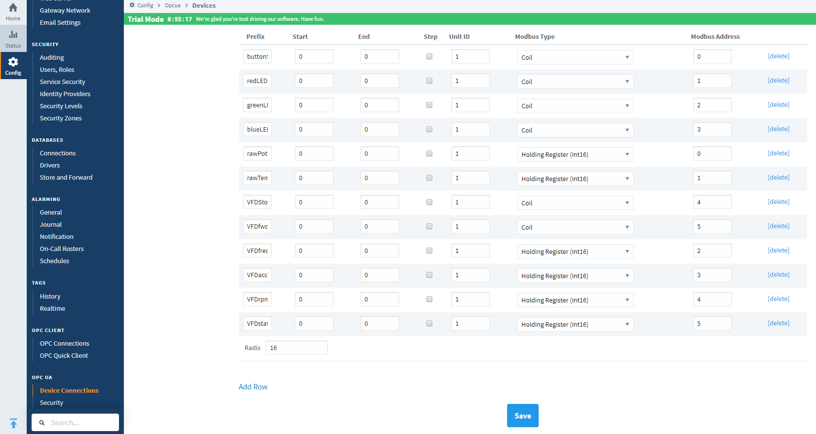
In the arduino modbus library and for use with Ignition, a coil (a single bit) and a holding register (16 bits) can both have the same address value i.e. two of them can be "0" but based on how they are implemented in the controller they are two physically different addresses.
If you want to connect to your Ignition gateway from a different PC in your home, you have to setup the self signature SSL certificate and open up inbound and outbound traffic for port 8088 in your firewall.

Here is the link to a video which quickly shows things working.
Industrial intelligence unleashed: Synchronizing frontline sensor data with professional enterprise SCADA.