Project Overview
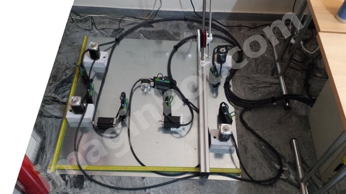
"Imaginbot-Core" is a rigorous implementation of Asynchronous CNC-Kinematics and Industrial Power-Topology. Designed explicitly to govern massive 1-cubic-meter 3D fabrication volumes, this project establishes a hyper-granular hardware architecture via the Arduino Mega 2560. The project explores the sophisticated routing of spatial G-Code vectors into localized, high-voltage stepping pulses. The build emphasizes absolute galvanic-isolation across seven distributed driver nodes (M1-M7), quad-Z axis synchronization analytics, and immense thermal-load mitigation.
BLOCK DIAGRAM
Connect the various modules that make up the system respecting this diagram attached in the SCHEMATICS section (at the bottom of the page).
Technical Deep-Dive
- Hyper-Scale Kinematic Orchestration:
- Distributed Stepper-Logic Array: Utilizing external, industrial-grade stepper drivers rather than inherently fragile onboard modules (e.g., A4988/DRV8825). Forensics involve the measurement of "Signal-Degradation Analytics"; the Mega 2560 pushes discrete 5V
PUL(Pulse),DIR(Direction), andEN(Enable) logical square-waves over isolated interconnects. The diagnostics focus on "Twisted-Pair Mitigation," strictly avoiding twisted logic-wires to prevent inductive cross-talk at extreme high-frequency pulse-rates across massive structural distances. - Quad-Z Axis Synchronization: Orchestrating a 1-cubic-meter gantry requires profound Z-axis stability. Forensics include the verification of "Concurrent-Step Latency"; utilizing four independent drivers (M3, M4, M5, M6) tied to parallel logic-channels, ensuring the immense weight of the print-bed is hoisted with mathematical precision, completely eliminating mechanical rack-and-pinion binding.
- Distributed Stepper-Logic Array: Utilizing external, industrial-grade stepper drivers rather than inherently fragile onboard modules (e.g., A4988/DRV8825). Forensics involve the measurement of "Signal-Degradation Analytics"; the Mega 2560 pushes discrete 5V
- High-Voltage Load-Isolation & Thermal Forensics:
- Multi-Rail Power Topography: Breaking the system into distinct, isolated domains: 5V Logic, Stepper 1-4 Power, and Extruder-Heater Power. The diagnostics focus on "Transient Ground-Bounce Avoidance," utilizing heavy-gauge mains-wiring and RC Line-Filters to ensure that the massive current-draw of the 40W+ heater cartridges and the huge NEMA motors does not induce a catastrophic brown-out on the Mega's ATmega2560 silicone die.
- Extruder & PID Thermal-Analytics: Managing the M15 (Heating Element) and M18 (Thermistor) nodes. The diagnostics focus on "Proportional-Integral-Derivative (PID) Calibration"; mapping the raw analog-to-digital voltage-drop across the thermistor to govern rapid, high-frequency PWM switching of a massive Power-MOSFET, maintaining 200°C+ thermal mass with sub-degree variance.
Download the Complete Manual
DOWNLOAD GERBER ORIGINAL FILES FOR FREE
to print the imaginbot 3D controller circuit
Download Gerber file to build the circuit
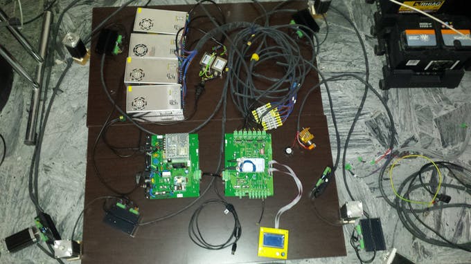
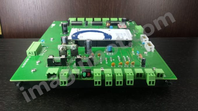
CONTROLLER CARD

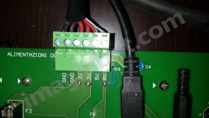
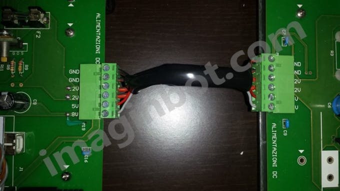
DC POWER SUPPLY
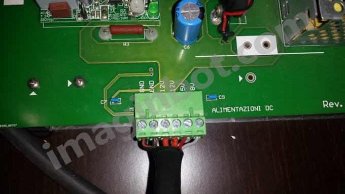
Use a six-wire cable to connect the power supply of the controller board (POWER SUPPLY connector) to the power supply board (POWER SUPPLY connector).
You can also use three pairs of cables.

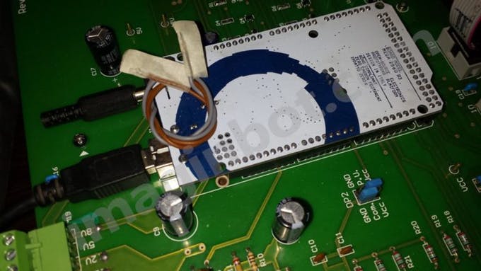
USB
Connect a common USB cable directly to the Arduino USB port.
STEP-BY-STEP DRIVERS
(CONNECTORS FROM M1 TO M7)
Use the four-wire cable for signals respectively:
Y1 (M1) and Y2 (M2) connectors: driver cables of the 2 motors on the Y axis.
Connectors Z1 (M3), Z2 (M4), Z3 (M5), Z4 (M6): driver cables of the 4 Z-axis motors.
Connectors X1 (M7): X-axis motor driver cables.
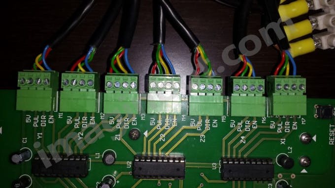
Follow this table for connecting the driver cables:
Screen printing on card --- Color
5V ---------------------- Red
PUL --------------------- Green
DIR --------------------- Yellow
EN ---------------------- Blue
The connectors are intended for the various drivers and can be wired with 0, 5 mm2 wire.
It is a good idea that the wire is not spirally wound (twisted) on the 4 connections relative to each driver.
The driving capacity of the various axes is expressed by the following table:
Axis-Connectors - Piloting capacity
X --------- M7 -------------- 1 driver
Y ------- M1, M2 ----------- 2 drivers
Z ---- M3, M4, M5, M6 ----- 4 drivers
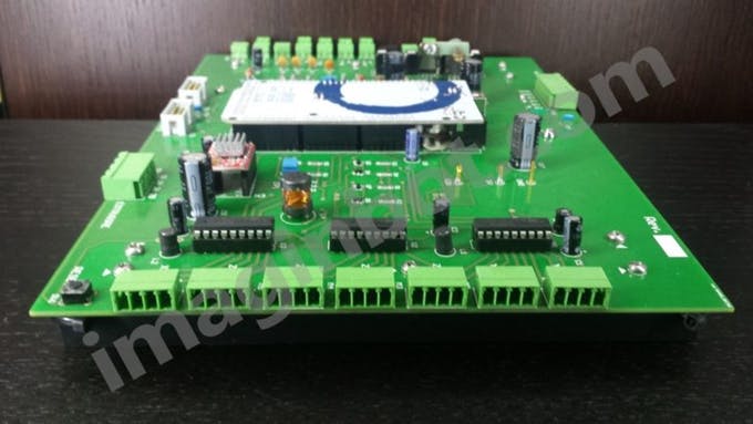
Engineering & Implementation
- Hardware-Topology & Interface Aesthetics:
- End-Stop Matrix (M9-M14): Establishing absolute zero-coordinates. Forensics include the measurement of "Hardware-Interrupt Debouncing," ensuring the physical switches limit catastrophic kinetic over-travel with zero computational latency.
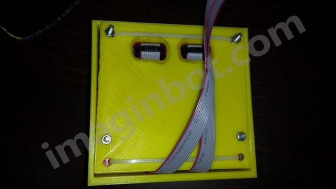
- HMI EXP1/EXP2 Diagnostics: Deploying a massive 12864 LCD and rotary-encoder subsystem over dual 10-pin ribbon cables. Forensics focus on "High-Speed SPI Integrity," maintaining an absolute cable-length maximum of 25cm to prevent the deterioration of the high-frequency rasterization data.
- System-Logic & Workflow Heuristics:
- The implementation demonstrates an "Industrial-Scale Aesthetic," proving that open-source microcontroller architectures scale perfectly into heavy-manufacturing geometry when paired with rigorous, properly segregated power electronics.
LIMIT SWITCH (END-STOP)
Use the two-wire cable to connect the limit switches respectively:
X-MIN (M9) and X-MAX (M10) connector: minimum and maximum X-axis limit switch.
Y-MIN connector (M11) and Y-MAX (M12): minimum and maximum Y-axis limit switch.
Z-MIN connector (M13) and Z-MAX (M14): minimum and maximum Z-axis limit switch.
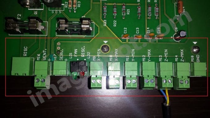
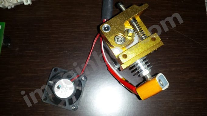
EXTRUDER
The extruder group includes several cables:
EXTRUDER connector (M8): Extruder four-wire stepper motor cable.
RISC connector (M15): Two-wire heating element cable.
TERM connector (M18): Two-wire thermistor cable.
VENT connector (M16): Two-wire fan cable (observe polarity).
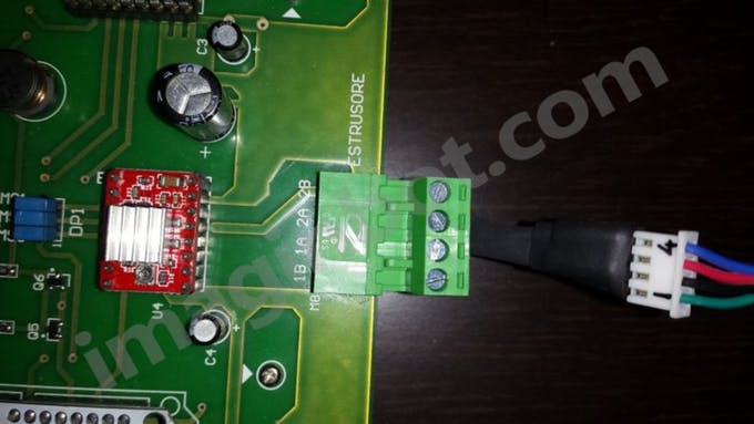
EXTRUDER MOTOR (M8 CONNECTOR)
This connector transfers the command pulses to the extruder's stepper motor.
Having to support about 1 A of current for each pin it is good to be wired with wires not less than 1 mm2 (18 AWG).
If the cable length exceeds 1m it is necessary to increase the section to 1.2 mm2.
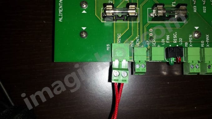
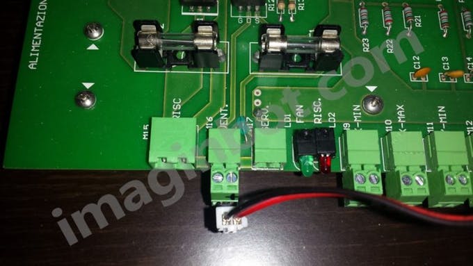
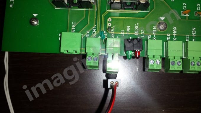
HEATING ELEMENT
(M15 CONNECTOR)
The 12 VDC power supply portal connector on the extruder heating resistance.
The wires must have a cross-section of at least 1.5 mm2.
Enabling is indicated by the red LED.
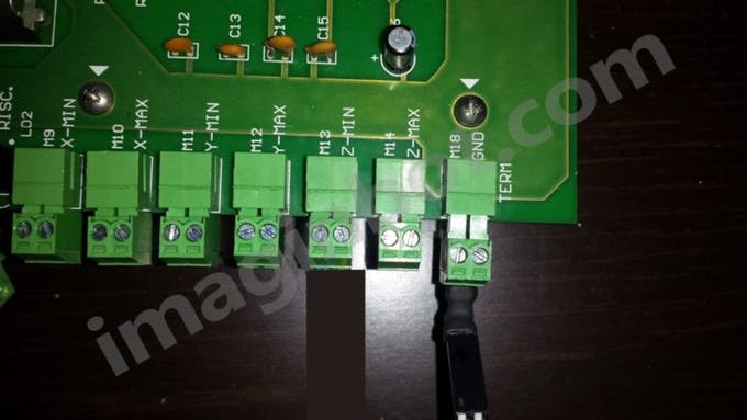
THERMISTOR (M18 CONNECTOR)
The connector collects the thermistor connections inside the extruder.
It is important that in the event of a connection coming from the thermistor is connected directly to the metal parts, it is connected to the right pin (if viewed from the front).
The right pin is grounded and can be distinguished in the general drawing because it has a square pad.
If in doubt, it is advisable to check whether one of the wires related to the thermistor really has a direct connection on the metal parts (extruder) and, in this case, proceed as indicated.
EXTRUDER FAN (M16 CONNECTOR)
This connector controls, via software, the fan present on the extruder.
The wires can be of section 0, 5 mm2.
The enabling of this fan is indicated by the green LED.
SERVICES (M17 CONNECTOR)
There are 12 service VDCs for a maximum current that can be drawn equal to 0, 4 A.
The polarity is marked with the "+" symbol on the screen printing.
This terminal can be used to connect any fans not controlled by the software (always active) also intended for cooling external power supplies.
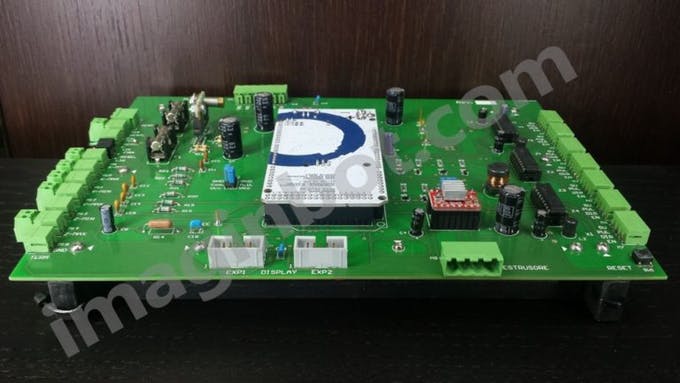
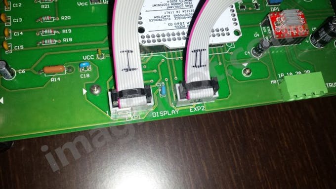
SD PLAYER DISPLAY (EXP1 AND EXP2)
The connectors have the task of connecting the display-encoder unit to the board.
Connect the 12864 display via its 10-wire flat cables.
Connect the first cable to the EXP1 connector and the second cable to the EXP2 connector.
Respect the right direction on both sides by orientating the cleat on the cable connector towards the slot on the connector on the board.
WARNING!
An incorrect arrangement of the same (can easily lend itself to being reversed between them) can cause irreversible damage.
The maximum length of the flat cable should not exceed 25cm.
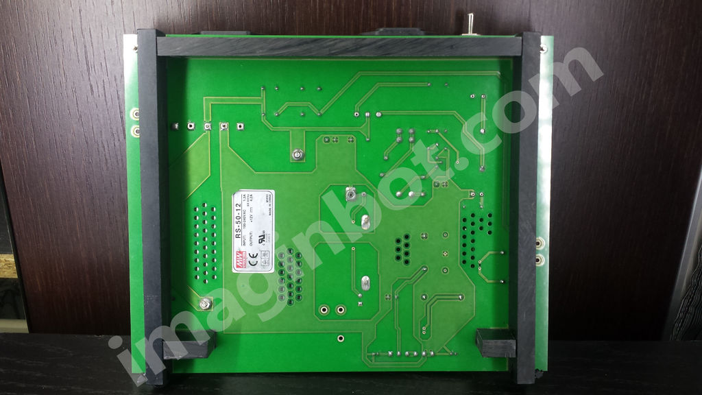
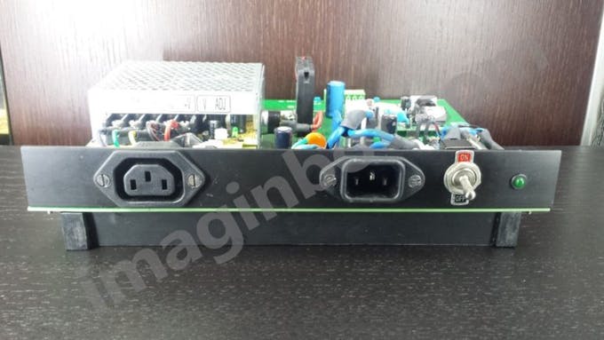
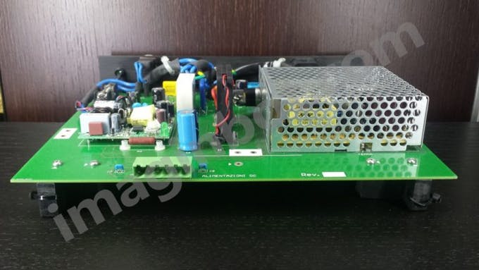
POWER SUPPLY CARD
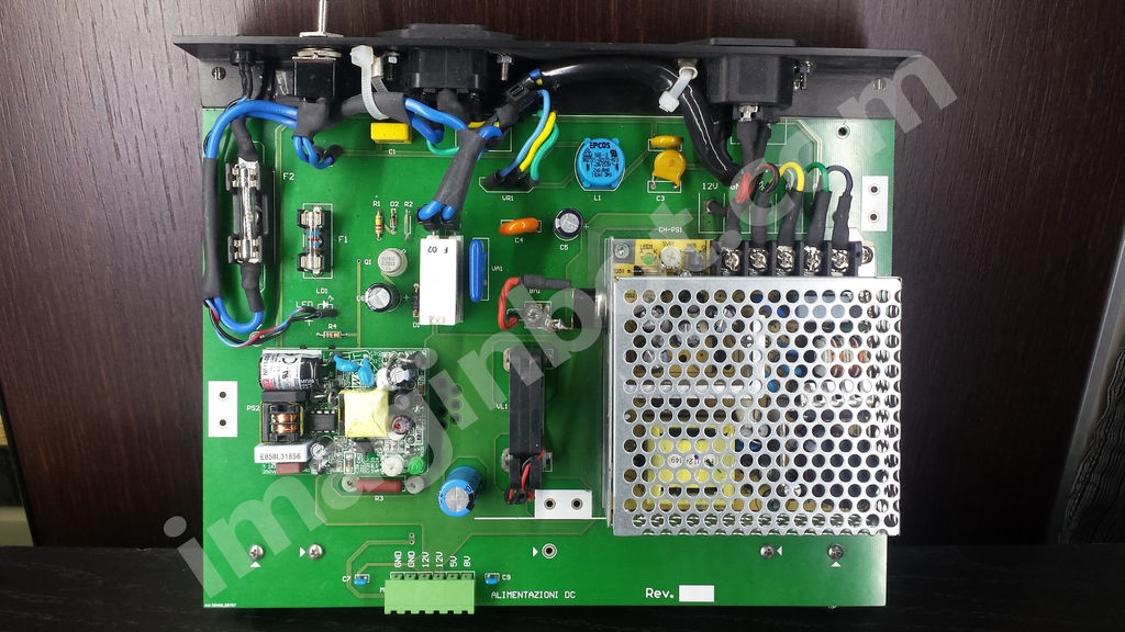
POWER SUPPLY CONNECTOR
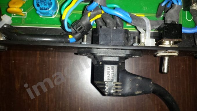
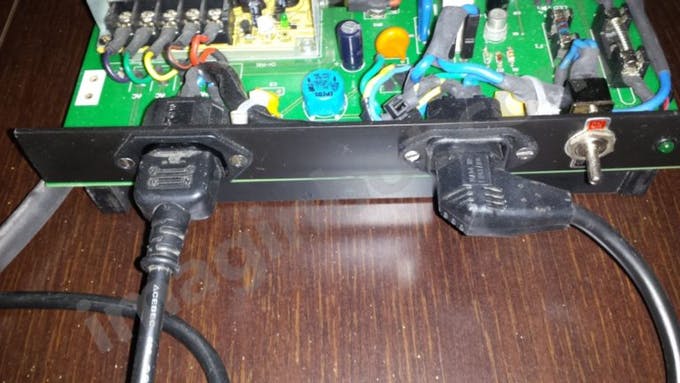
INPUT FROM ELECTRICITY NETWORK
Present on the front panel, it supplies AC power to both the external board and the power supplies.
It can be wired with a female connector for IEC type tray, commonly available.
The cable must not have a section less than 1.2 mm2 and must be equipped with earth.
A common 220VAC cable for fixed computers can be used.
Before connecting the cable, make sure that the main switch is OFF and that the card is inside an insulating container so as to protect.
DC OUTPUT FOR POWER SUPPLY
CONTROLLER CARD
Use the cables recommended in the table at the end of this document to connect the two boards together, Controller and Power Supply.

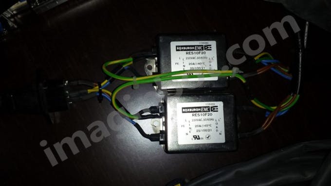
RC FILTERS
Connect the 220VAC inputs of the two RC filters with a common monitor cable to the connector on the 220VAC output power supply board.
Each cable must have three conductors:
Phase (brown).
Neutral (blue).
Earth (green and yellow).
The inputs of the filter 1 and filter 2 can be connected in parallel.
ข้อมูล Frontmatter ดั้งเดิม
apps:
  - "Arduino IDE (Firmware Compilation)"
  - "SD Player/Encoder Display (HMI Telemetry Dashboard)"
author: "imaginbot"
category: "Motors & Robotics"
components:
  - "1x Custom Imaginbot PCB Shield (High-Density Routing Substrate)"
  - "1x Arduino Mega 2560 (Primary Interpolation-Compute Hub)"
  - "Multiple External Stepper Drivers (High-Voltage Actuator Nodes)"
  - "Multiple 12V/24V Industrial Power Supplies (Independent Rail-Topology)"
  - "NEMA Stepper Motors [X, Y, Z Axis Array] (Kinematic Endpoints)"
description: "A profound industrial-level CNC processing engine featuring Mega 2560 G-Code parsing, hyper-scale stepper motor vectoring (M1-M7), and rigorous high-current load-isolation."
difficulty: "Intermediate"
documentationLinks: []
downloadableFiles:
  - "https://projects.arduinocontent.cc/44634a2e-d8a9-4cf1-aea2-fe1f3cd99bee.zip"
  - "https://projects.arduinocontent.cc/44634a2e-d8a9-4cf1-aea2-fe1f3cd99bee.zip"
encryptedPayload: "U2FsdGVkX194KPaJeP/iBc0OaSsb5fuTSiF3r80LCsVX+awSHfqbeCQ+zS+zCR55kVnz903PTOU4ApasIJ8+hYl2Xviaeta0M/27m7gvFnM="
heroImage: "https://cdn.jsdelivr.net/gh/bigboxthailand/arduino-assets@main/images/projects/imaginbot-controller-for-1-cubic-meter-3d-printer-c83b56_cover.jpg"
lang: "en"
likes: 1325
passwordHash: "1f0229c30167a2c15b96fbd5efb063d1d8118241cb00568774295869e989ed79"
price: 2450
seoDescription: "Imaginbot Controller for 1 Cubic Meter 3D Printer. Designed to control large-scale stepper motors for high-volume 3D printing."
tags:
  - "hyper-scale-cnc-orchestration"
  - "multi-axis-stepper-kinematics"
  - "high-current-load-isolation"
  - "g-code-parsing-forensics"
  - "arduino-mega-2560"
title: "Imaginbot-Core: Asynchronous CNC Orchestration & High-Current Kinematic Diagnostics"
tools:
  - "Marlin/RepRap Firmware (G-Code Spatial Analytics)"
  - "End-Stop Threshold Validation (Collision-Mitigation Heuristics)"
videoLinks:
  - "https://www.youtube.com/embed/UdN6qVLs8tQ"
views: 1325