USB/IR cable that turns on your audio receiver or home teatre system after you power on the TV.
I wanted to automatically turn on the Marantz PM6006 amplifier whenever the Samsung TV is powered via standard IR remote or the (WOL) Wake on LAN feature.
When TV is powered on, the ATtiny85 chip gets 5V from TV USB port and sends RAW RC5 IR code, which in turn powers on the Marantz amplifier.
As audio receiver has enabled power save feature, it goes to standby automatically when no input is detected (TV is turned off). Also the volume is controlled with samsung infrared remote (Universal Remote feature).
That said this project adds missing part to the system - auto power on
Project Overview
The "Zero-User-Intervention Audio Bridge" is an ingenious home automation solution that synchronizes high-end audio receivers with modern smart TVs. Many audiophiles face the "Second Remote" problem where a TV powers on via Wake-on-LAN (WoL) or a standard remote, but the associated amplifier remains in standby. By repurposing a USB cable and embedding an ATtiny85 microcontroller, this project detects when the TV's USB port receives power and immediately transmits a pre-recorded Infrared (IR) "Power On" command to the receiver. It is a masterclass in minimalist hardware hacking and efficient firmware design.
Technical Deep-Dive
- The ATtiny85 Advantage: While the project uses an Arduino UNO for development and programming, the final implementation uses the ATtiny85. This 8-pin microcontroller is ideal for "Single-Task" automation because of its tiny footprint and low power consumption. By using the "Arduino as ISP" configuration, the UNO acts as a bridge to flash the custom firmware into the ATtiny's internal memory.
- RAW IR Code Capture: Standard IR libraries often fail with high-end audio equipment that uses proprietary or high-bitrate protocols (like complex RC5 or Marantz variants). This project bypasses protocol decoding by capturing the RAW pulse-width timings. Using a TSOP31238 receiver, the system measures the exact microsecond duration of the light "On" and "Off" states, storing them in an integer array (
unsigned int irSignal[]). This ensures a 100% accurate reproduction of the original remote's signal. - Trigger-to-Action Firmware: The logic is centered entirely in the
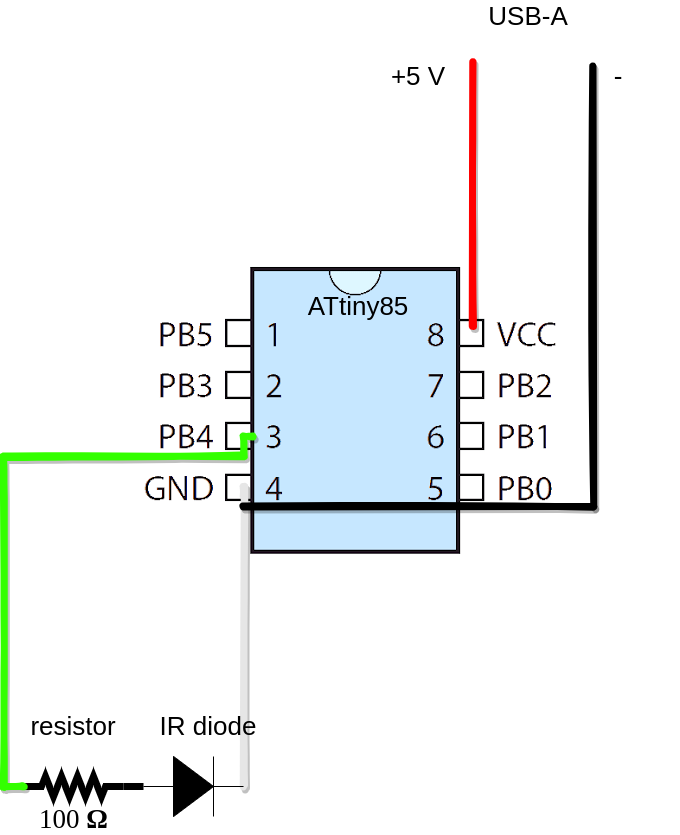
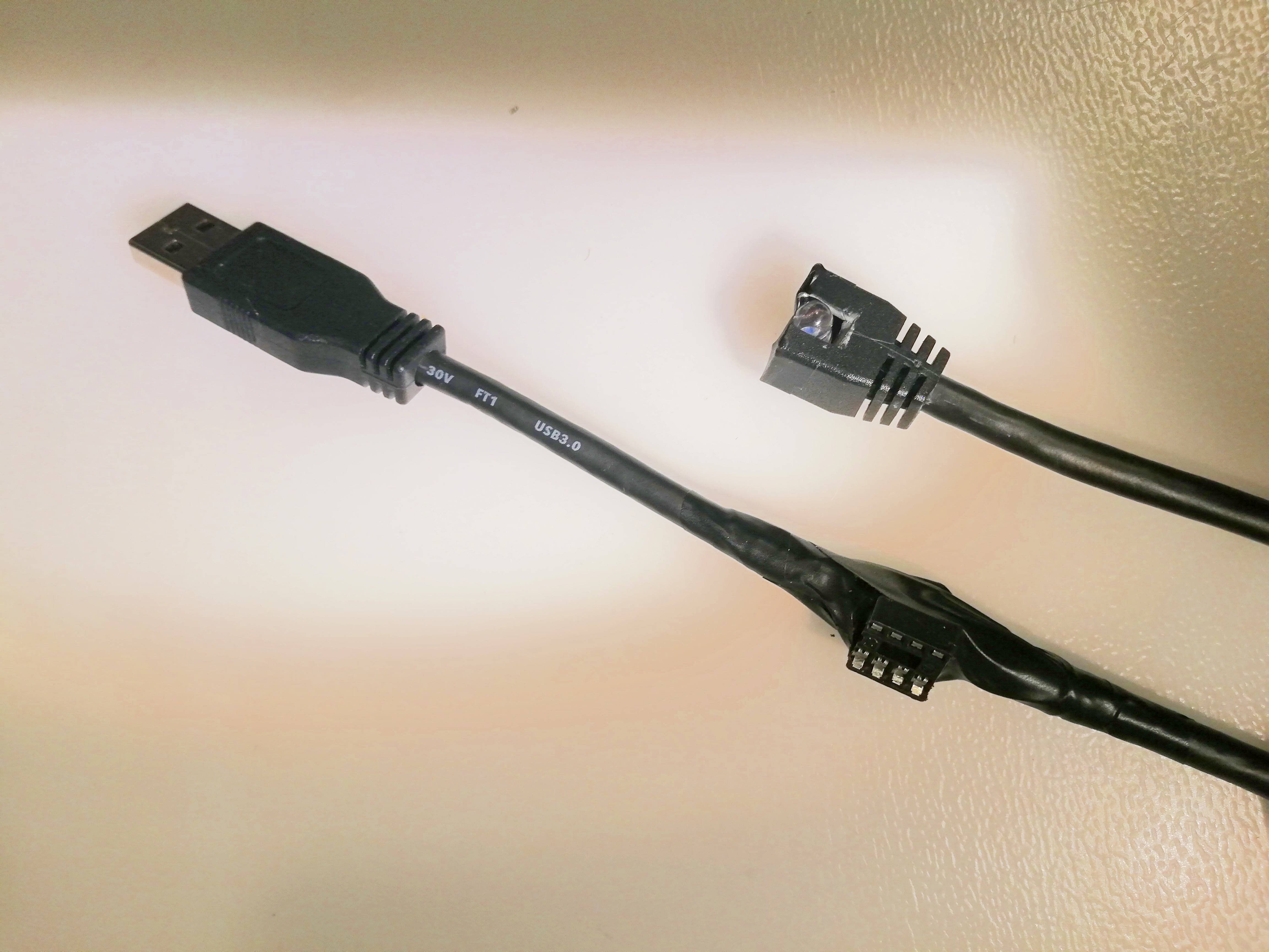
setup()function. Because the ATtiny is powered directly by the TV's 5V USB rail, the microcontroller "boots" the instant the TV turns on. The firmware immediately shoots the IR signal twice (ensuring the receiver catch it during its own power-up phase) and then stays in a passive state. This "one-shot" approach requires zero maintenance and zero battery power. - Hardware Modding & USB Pin-Tapping: The project involves carefully stripping a passive USB cable to access the internal wires. The Red (+5V) and Black/White (GND) lines provide the power supply, while a internal data line is repurposed to carry the decoded IR modulation to the emitter LED located at the other end of the cable.
Engineering & System Synergy
- Complete Automation Loop: This project completes the automation cycle without requiring complex Smart Home hubs. The TV powers the cable, the cable powers the Marantz amp, and the Marantz amp’s built-in "Auto Standby" feature handles the shutdown once the TV signal stops.
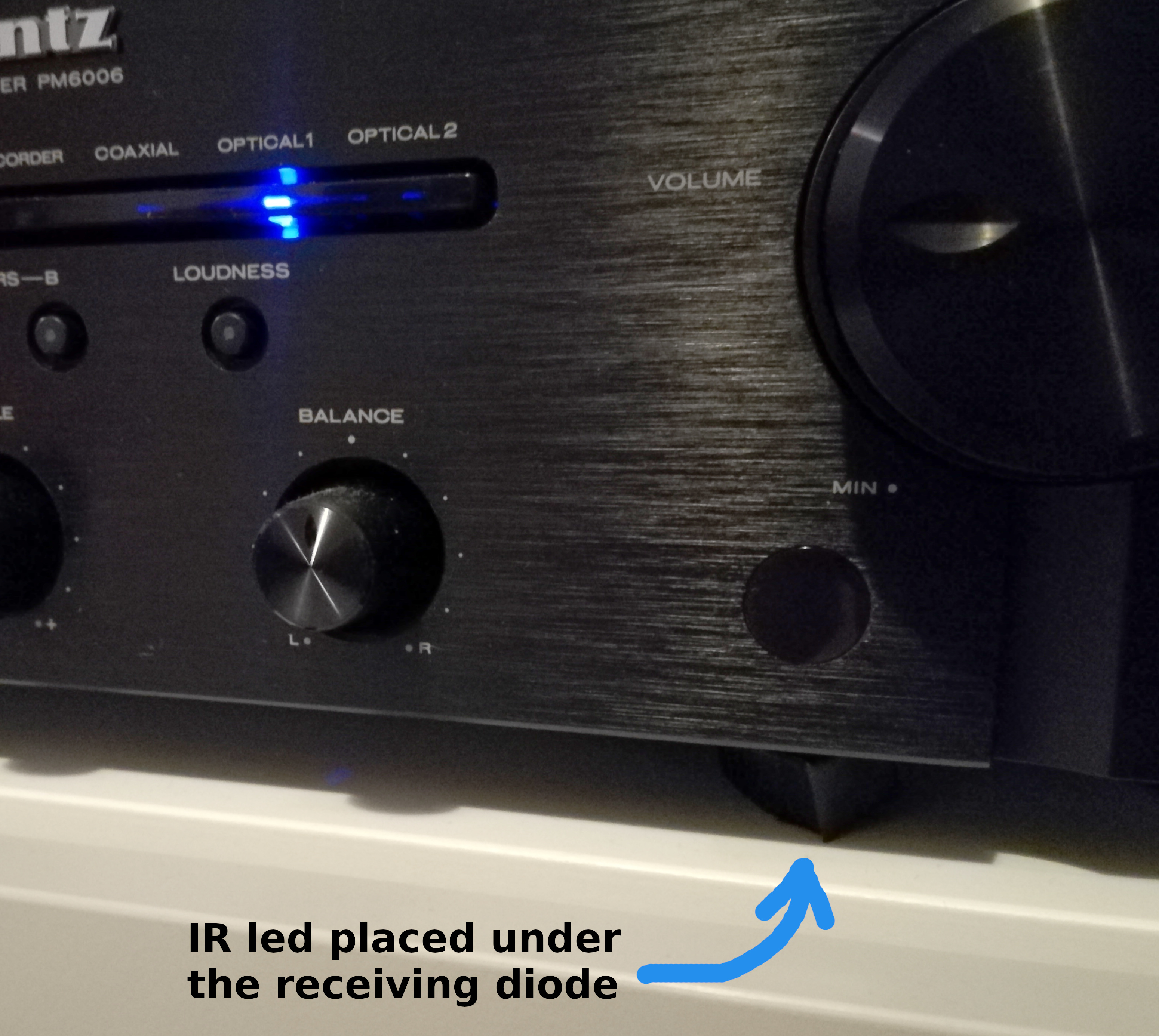
- Non-Invasive Installation: The IR emitter is small enough to be hidden in the mechanical gap between the receiver's faceplate and chassis, maintaining the sleek aesthetic of a high-end Hi-Fi setup.
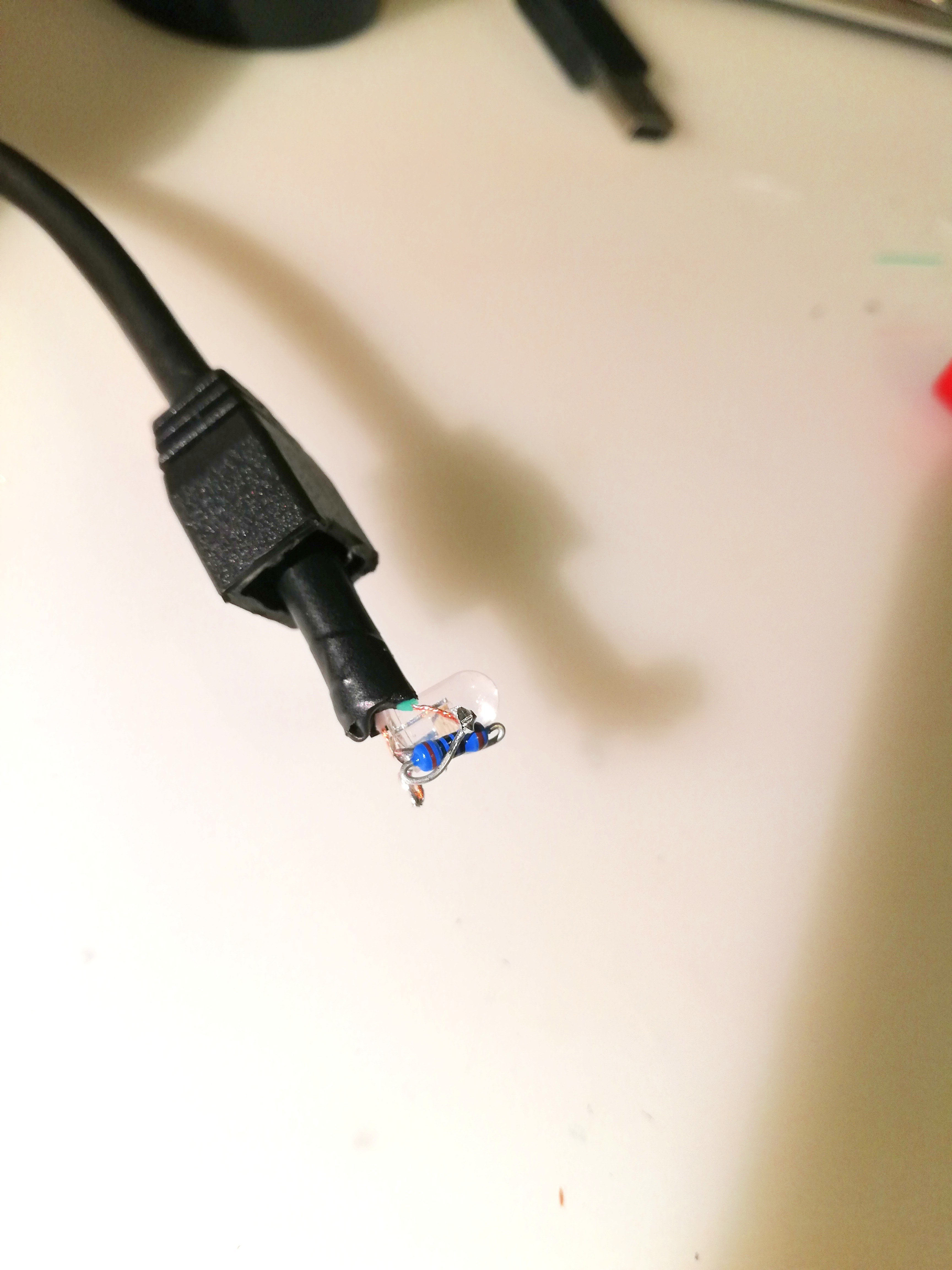
- Circuit Protection: A 100 ohm resistor is placed in series with the IR LED to limit current draw, protecting the ATtiny85's I/O pins while still providing enough optical power for reliable 36kHz or 38kHz transmission.
- Broad Compatibility: While demonstrated with a Marantz amplifier, this logic can be applied to any IR-controllable device (Projectors, AC units, or older stereo systems), making it a universal "Power Syncer."
1. Make the cable
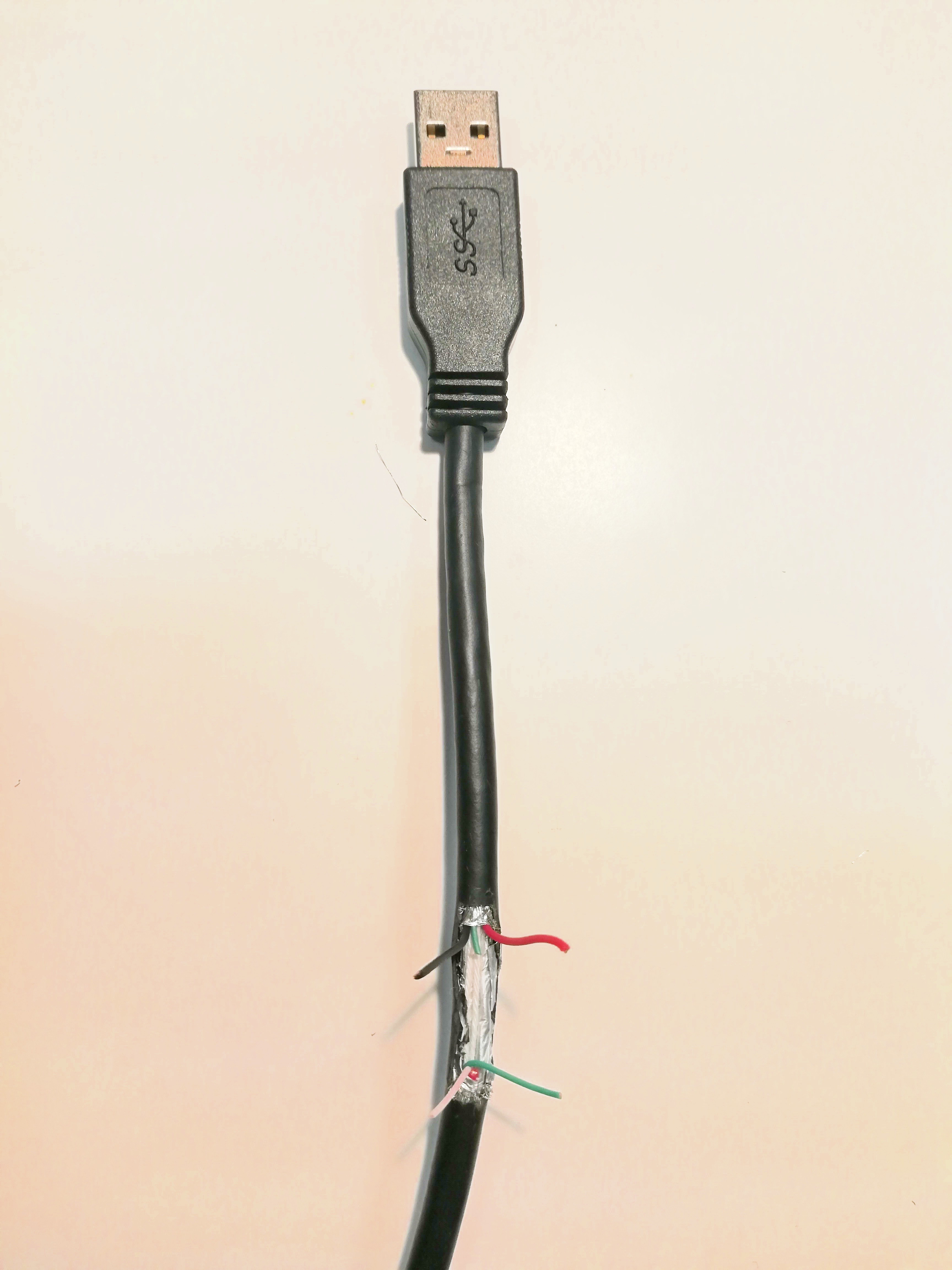
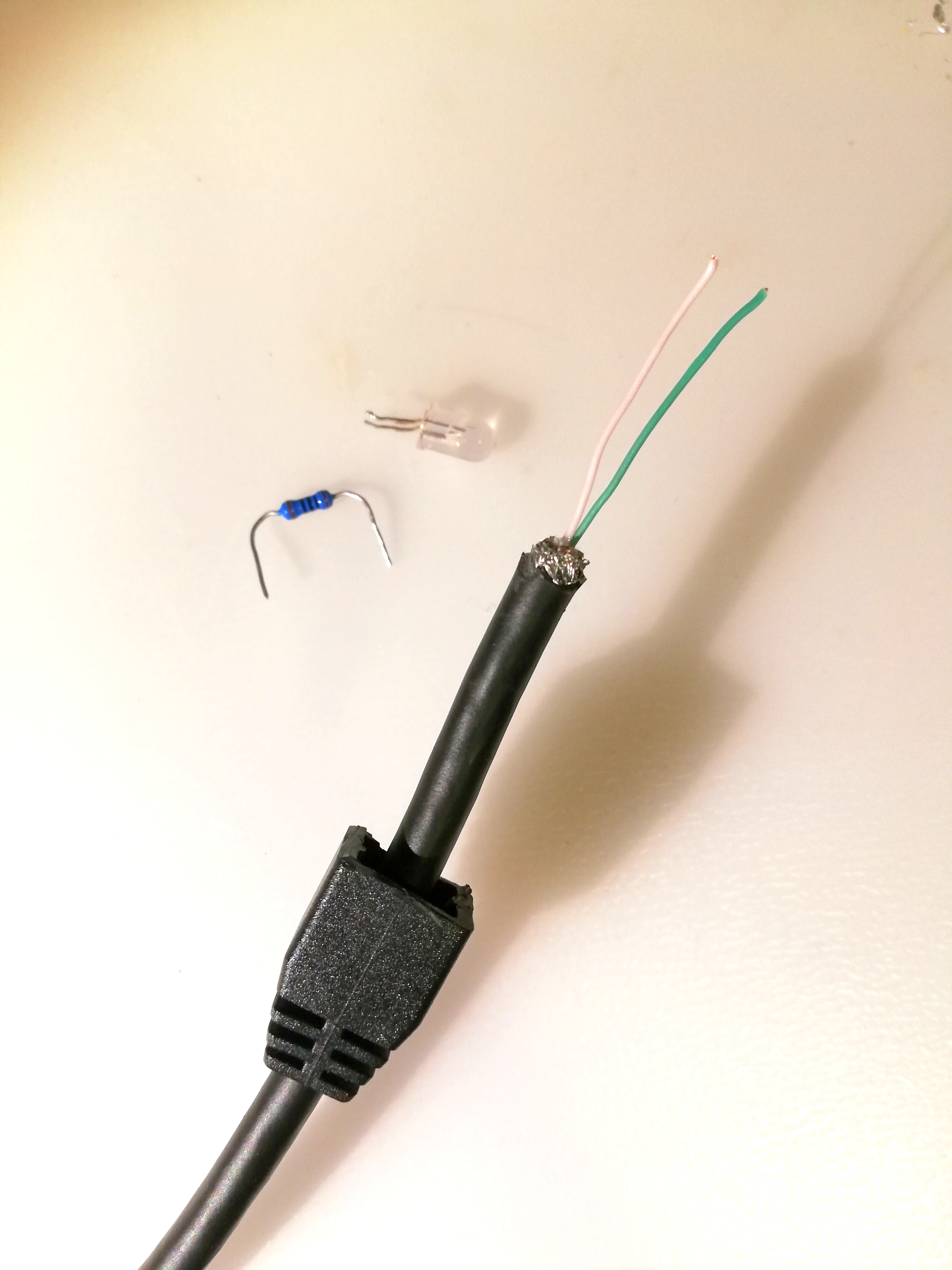
Open the cable insulation for about 2 cm. In this example the USB 3.0 A to B Cable is used, but any USB-A cable will do.
Select the 4 wires:
- black and white wire will be ground (GND)
- red wire is +5V
- green wire for sending IR impulses to diode from ATtiny85
1.1 Insulate unused wires and solder chip socket on the cable
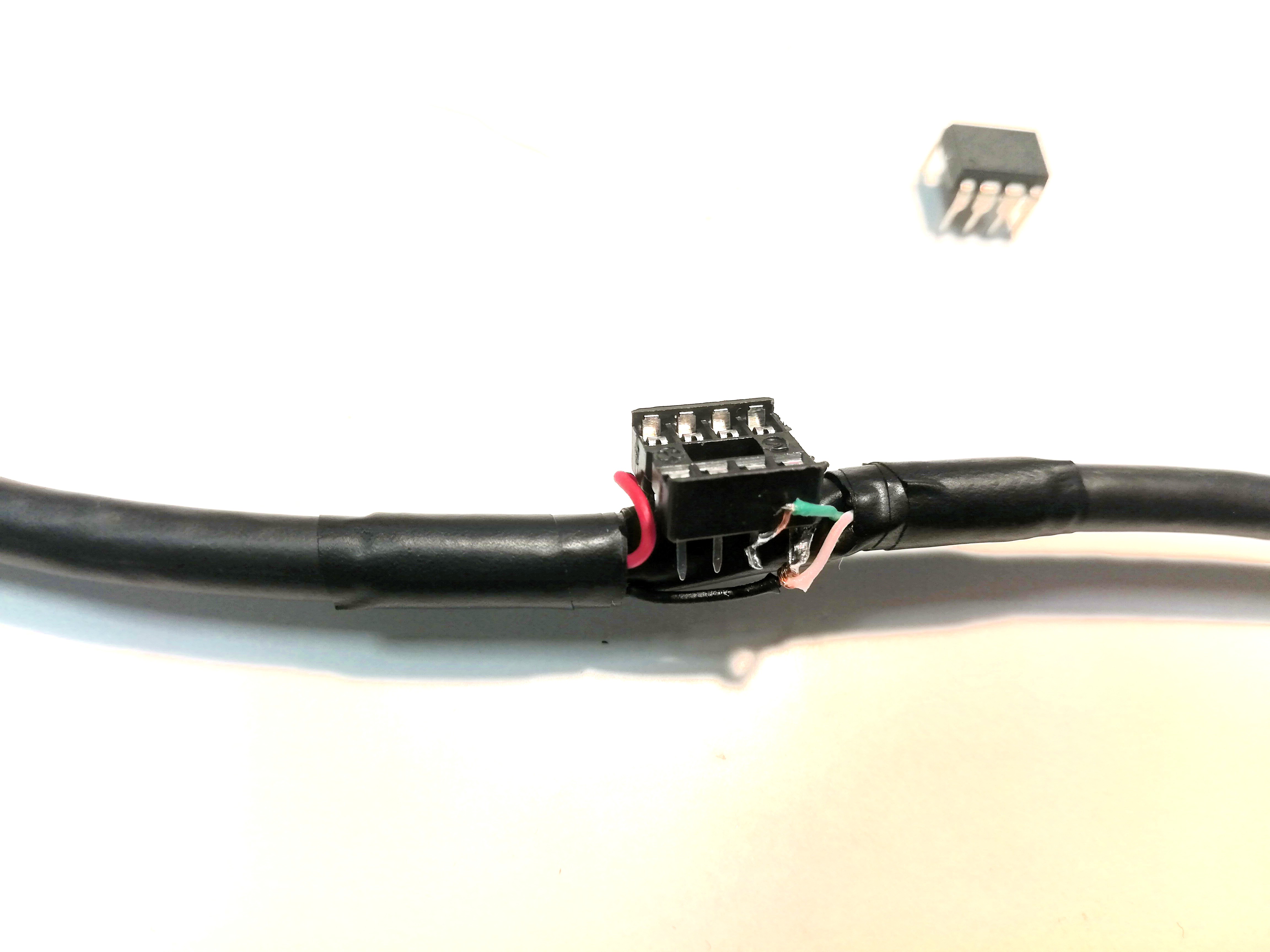
Solder wires using this simple color coded diagram:
1.2 Strip the other end of cable to prepare it for resistor and ir led soldering
1.3 Solder resistor and led
1.4 Finished hardware
2 Get your RAW IR code from original remote
- Wire the IR receiver diode to Arduino UNO board

- Upload examples/IRreceiveDump/IRreceiveDump.ino from IRremote examples sketches to Arduino UNO
- Capture the RAW IR code while presing the power button on your original device IR remote and save it in text file for later use in the code.
2.1 Prepare UNO and ATtiny as described in the video
Follow this great youtube video:
Warning ! If burning the boot-loader is done incorrectly it may render your chip unusable.
Summary of tasks:
- Upload "Arduino as ISP sketch" to UNO so it becomes ISP programmer
- Install ATtiny board support in Arduino IDE and burn the settings to the chip (links in code section)
- Install IRremote library in Arduino IDE (links in code section)
- wire the UNO and ATtiny85
2.2 Upload the code to ATtiny 85 and enjoy !
#include <IRremote.h>
IRsend IrSender;
void setup() {
 int khz = 36;
 unsigned int irSignal[] = {900, 900, 850, 900, 850, 900, 1750, 900, 850, 950, 850, 900, 850, 900, 850, 900, 900, 1750, 850, 950, 1700, 950, 850};
 IrSender.sendRaw(irSignal, sizeof(irSignal) / sizeof(irSignal[0]), khz);
 delay(1000);
 IrSender.sendRaw(irSignal, sizeof(irSignal) / sizeof(irSignal[0]), khz);
}
void loop() {
}
The raw code in {} brackets is for powering on the Marantz PM6006 amplifier. You can replace it with your code from step 2.
2.3 Place IR led near receiving diode and connect USB to TV
This particular model has small gap under the front mask so the ir signal can get to it.